Firearm grip

a grip and firearm technology, applied in the field of firearms, can solve the problems of extreme rapid pressure increase, pressure increase and concomitant temperature increase in the system, and the level of energy required

Inactive Publication Date: 2011-08-04
GRAUER SYST
View PDF2 Cites 57 Cited by
  • Summary
  • Abstract
  • Description
  • Claims
  • Application Information

AI Technical Summary

Benefits of technology

[0011]The present invention provides an advantage to police officers, servicepersons, and responsible civilians who use a style of rifle which includes a forward magazine well such as is present on those commonly known as M16 or AR-15 style rifles. These would include variations of these including at least the AR15, M16A1, M16A2, M16A3, M16A4, M4, M4A1, H&K 416, FN SCAR, and XM8 rifles.

Problems solved by technology

In these more modern firearms, when the firing pin of the firearm strikes the cartridge's primer, the primer ignites the powder within the shell, causing an extremely rapid pressure increase, which causes the projectile to dislodge from the shell's open end, driving the projectile down the barrel of the firearm and out the end of the muzzle toward its target.
This constant volume expansion causes both a pressure increase and a concomitant temperature increase within the system.
This level of energy requires powders and loads that generate great temperatures and pressures within the barrel.
Also an issue is the high recoil of the high-pressure, heavy bullet systems common today.
These great recoils are not only sometimes uncomfortable or even damaging to the shooter, but greatly affect accuracy, target reacquisition, and sight realignment between shots.
Recoil and firearm control is especially an issue in tactical close quarter combat (CQC) or close quarter battle (CQB) situations, such as is very typical in urban warfare settings or in police or SWAT operations.
Tactics are complicated by a three-dimensional environment, limited fields of view, and fire because of buildings, enhanced concealment and cover for enemy forces or criminals, below-ground infrastructure, and the ease of placement of traps and snipers.

Method used


Image

  • Firearm grip
  • Firearm grip
  • Firearm grip

Examples


Embodiment Construction

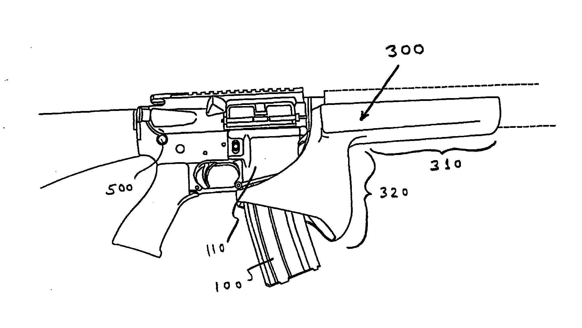
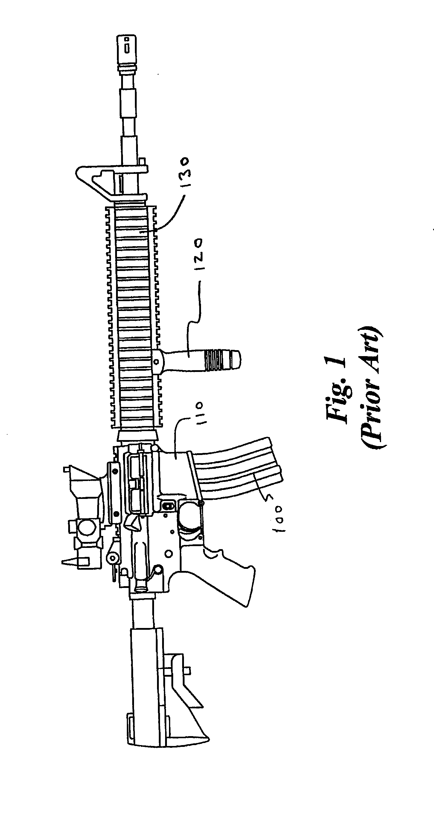
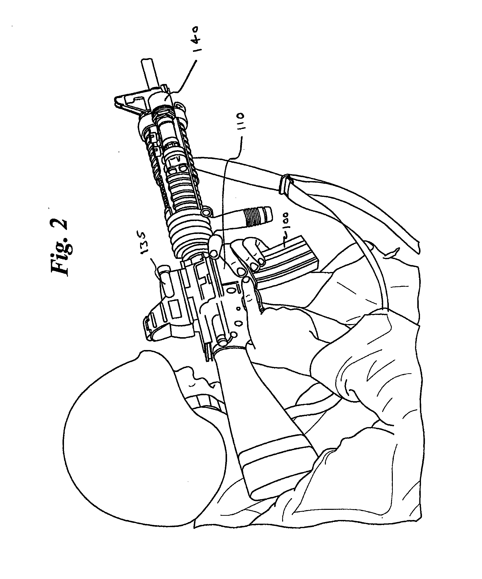
[0044]The present invention includes several features to improve firearm performance and allow a user of the firearm to achieve a stable, controlled grip on the firearm while also maintaining a minimized silhouette. It includes a grip assembly having a portion adapted to extend generally downward along at least a part of the front of the magazine well so as to prevent the insertion of any part of the hand of the user between the grip and the front of the magazine well. The grip is configured so as to not interfere with the pivoting relationship between the weapon upper and weapon lower during partial or complete disassembly of the weapon. The grip may be removable, partially removable, or adjustable in such a way as to allow relative movement between the upper and lower. The present invention is applicable to any style of rifle which includes a forward magazine well such as is present on those commonly known as M16 or AR15 style rifles, including variants such as H&K 416, FN SCAR, a...


PUM


Abstract

An integrated grip and rail system is provided. Included is a firearm and the firearm grip. The grip is configured to be disposed in front of the magazine well and provide a stable grip point which does not allow a user's thumb or other appendage to be disposed between the grip and magazine well. The grip is configured so as to not interfere with the pivoting relationship between the weapon upper and weapon lower during partial or complete disassembly of the weapon. The rear region may also have a portion extending rearward along at least part of each side of the magazine well to form feed ramps as a part of the magazine well extension. Included is a magazine well extension mechanically coupled to a forearm rail system for mounting to the firearm.

Description

CROSS REFERENCE TO RELATED APPLICATIONS[0001]This application claims the benefit of earlier filed U.S. Provisional Patent Applications 61 / 082,290 filed Jul. 21, 2008 and 61 / 144,557 filed Jan. 14, 2009, both of which are hereby incorporated herein in their entireties.FIELD OF INVENTION[0002]The present invention relates to firearms, and more specifically to firearm grips and how their design affects the performance of the firearm.BACKGROUND OF INVENTION[0003]Since the 13th century, firearms have operated on the principle that an explosive mass of powder, generally referred to as gun powder, could be ignited and caused to react and rapidly expand, causing a sudden increase in pressure within a confined and defined space. This initially constant volume pressure increase was caused to happen behind a projectile, which was then forced in the one direction it could move, along with the reacting gas, which was down a barrel and out the end of a firearm muzzle. Early firearms were loaded do...

Claims


Application Information

Patent Timeline
Patent Type & Authority Applications(United States)
IPC IPC(8): F41C23/16F41C23/22
CPCF41C23/16F41C23/12
Inventor BRIXIUS, JOHN
Owner GRAUER SYST
Why Eureka
Try Eureka