Cooling apparatus and frost detecting method thereof

a technology of cooling apparatus and frost detection, which is applied in the direction of domestic cooling apparatus, refrigeration machines, defrosting, etc., can solve the problems of excessive power consumption, inefficient removal method of frost formed on the evaporator, and inability to detect so as to accurately determine the amount of frost formed, accurately determine the noise contained in the signal received, and achieve the effect of easy and accurate determination

Inactive Publication Date: 2011-08-04
SAMSUNG ELECTRONICS CO LTD
View PDF8 Cites 17 Cited by
  • Summary
  • Abstract
  • Description
  • Claims
  • Application Information

AI Technical Summary

Benefits of technology

[0038]In accordance with one aspect, it may be possible to easily and accurately determine noise contained in a signal received from the frost sensor by determining, as noise, the signal received from the input terminal, to which the frost sensor is not connected, and subtracting the noise from the signal received from each input terminal, to which the frost sensor is connected.
[0039]As a result, it may be possible to accurately determine whether or not frost has been formed on an evaporator, and to accurately detect the amount of frost formed.
[0040]It may also be possible to execute a defrosting operation at an appropriate point in time as the accuracy of the detection of the amount of frost formed on the evaporator is enhanced. Accordingly, it may be possible to prevent the cooling efficiency of the evaporator from being reduced due to a reduction in air flow rate during heat exchange.
[0041]It may be possible to accurately determine the amount of frost left on the evaporator during the defrosting operation, and thus to accurate determine an appropriate point in time when the defrosting operation should be ended. Accordingly, it may be possible to end the defrosting operation at an appropriate point in time. As a result, it may be possible to reduce energy consumption caused by the defrosting operation. Also, the temperature variation in the cooling apparatus may be minimized in accordance with the defrosting operation. Accordingly, the performance of the cooling apparatus may be enhanced.
[0042]As the defrosting operation may be efficiently begun and ended, the heater may be driven only when the driving of the heater is required. Accordingly, the driving time of the heater and the number of times the heater drives may be reduced.

Problems solved by technology

As a result, the heat exchange efficiency of the cold air flowing around the evaporator is degraded, thereby causing degradation in cooling efficiency and excessive power consumption.
However, this method is inefficient to remove the frost formed on the evaporator because the defrosting operation is periodically carried out based on the operating time of the compressor, irrespective of the actual amount of the frost formed on the evaporator.
Furthermore, unnecessary power consumption may occur.
Also, an increase in temperature may frequently occur due to the defrosting operation.
In such a frost detecting apparatus, noise may be generated due to variation in heat generated in various elements such as a multiplexer and a detector.
As a result, it may be difficult to accurately determine the amount of frost.
For this reason, it may be difficult to carry out a defrosting operation at an appropriate point in time.

Method used


Image

  • Cooling apparatus and frost detecting method thereof
  • Cooling apparatus and frost detecting method thereof
  • Cooling apparatus and frost detecting method thereof

Examples


Embodiment Construction

[0053]Hereinafter, exemplary embodiments will be described in order to explain the present invention by referring to the figures.

[0054]Exemplary embodiments are adapted to enhance the defrosting efficiency of a cooling apparatus and thus to reduce power consumption by accurately detecting whether or not frost has been formed on an evaporator of the cooling apparatus and the amount of frost formed, and controlling driving of a heater based on the results of the detection, thereby controlling a defrosting operation.

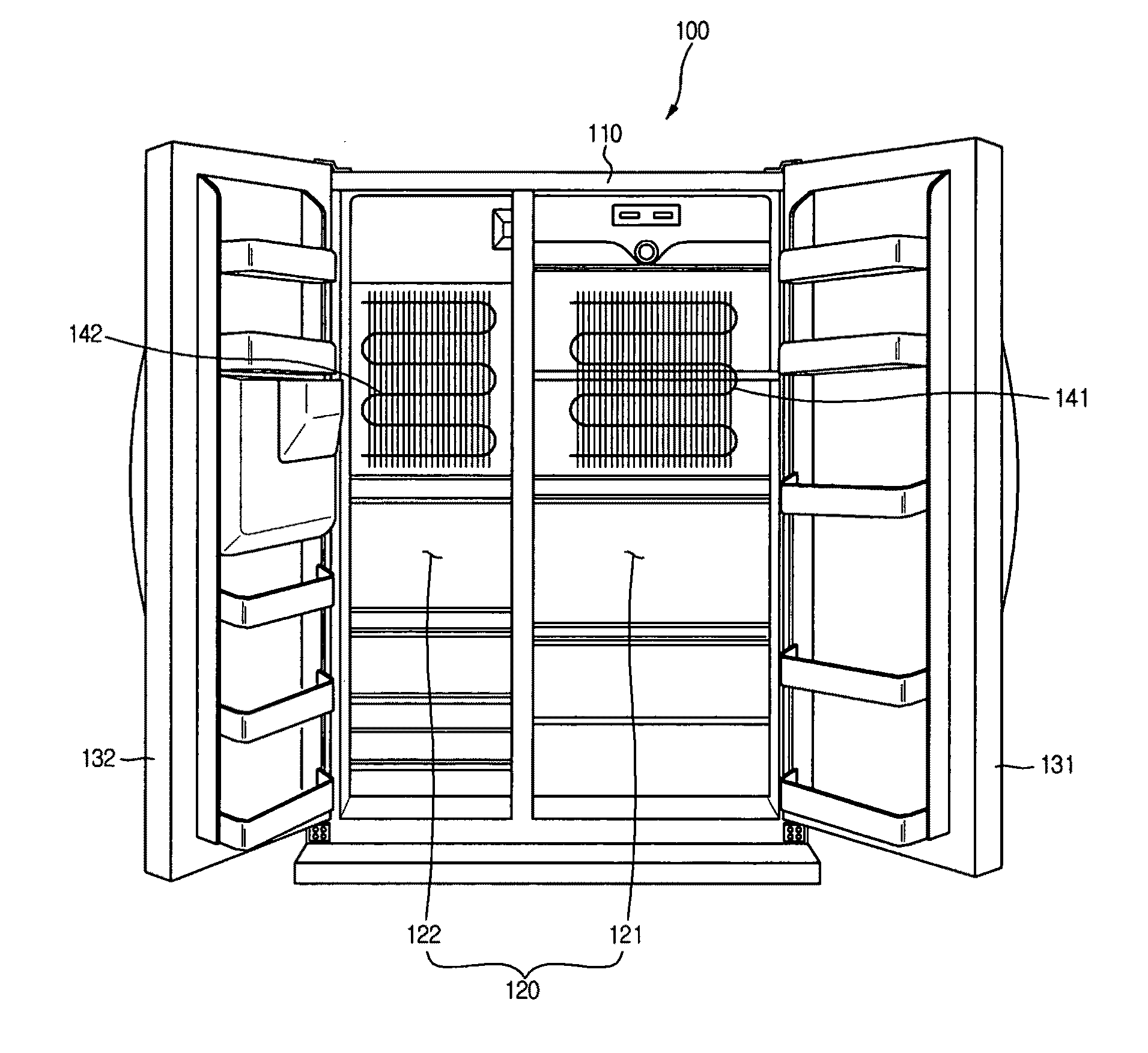
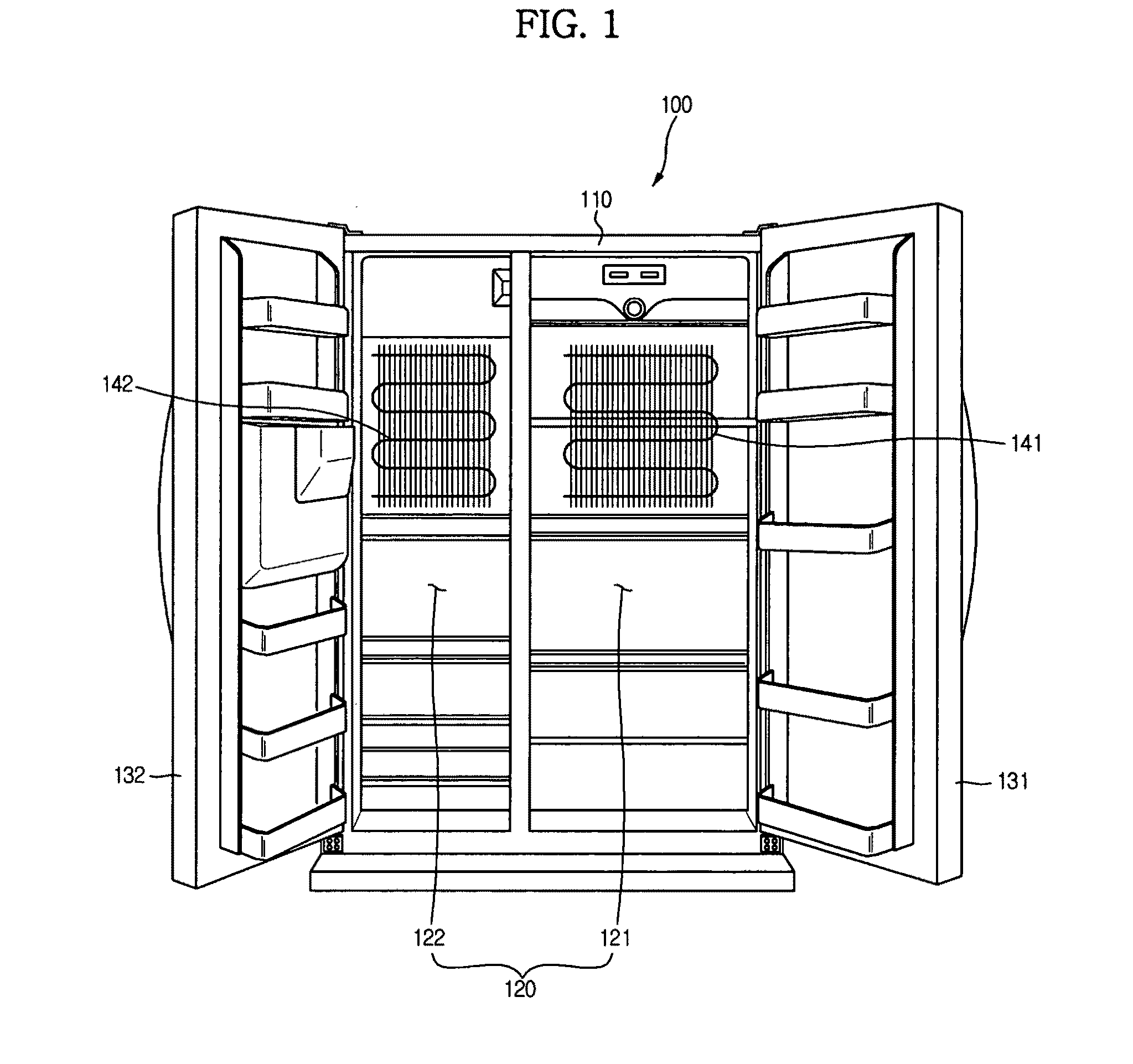
[0055]The exemplary embodiments are described in conjunction with an example in which the cooling apparatus is applied to a refrigerator.

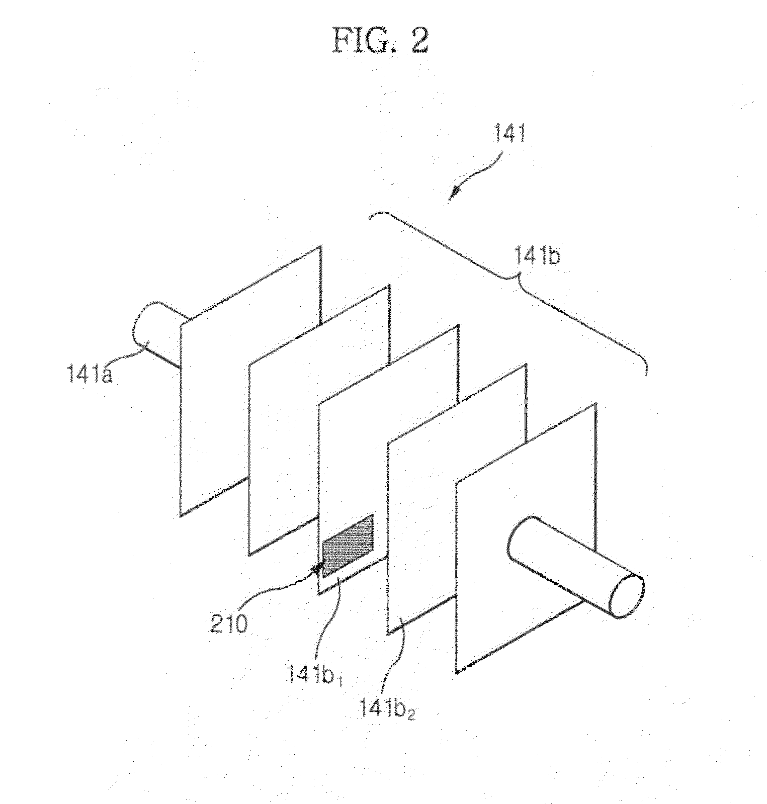
[0056]FIG. 1 is a view illustrating a refrigerator according to an exemplary embodiment. FIG. 2 is a view illustrating a detailed configuration of an evaporator provided at the refrigerator according to the illustrated embodiment. FIG. 3 is a block diagram illustrating a control configuration of the refrigerator according to an exemplary e...


PUM


Abstract

A cooling apparatus including a frost sensor to sense frost, a multiplexer having a first input terminal, to which the frost sensor is connected, and a second input terminal as a non-connected input terminal, a signal processor to subtract a signal input through the second input terminal from a signal input through the first input terminal, and to output a signal obtained by the subtraction, and a controller to detect an amount of frost sensed by the frost sensor, based on the output signal from the signal processor. It is possible to easily and accurately determine noise contained in a signal received from the frost sensor by determining, as noise, the signal received from the input terminal, to which the frost sensor is not connected, and subtracting the noise from the signal received from each input terminal, to which the frost sensor is connected.

Description

CROSS-REFERENCE TO RELATED APPLICATIONS[0001]This application claims the benefit of Korean Patent Application No. 2010-8391 filed on Jan. 29, 2010 in the Korean Intellectual Property Office, the disclosures of which are incorporated herein by reference in its entirety.BACKGROUND[0002]1. Field[0003]Embodiments relate to a cooling apparatus and a frost detecting method thereof, and, more particularly, to a cooling apparatus capable of directly detecting frost formed on an evaporator due to heat exchange and a frost detecting method thereof.[0004]2. Description of the Related Art[0005]A cooling apparatus is adapted to cool a confined space by circulating a refrigerant through a refrigeration cycle. As such a cooling apparatus, there are a refrigerator, a Kimchi refrigerator, an air conditioner, etc.[0006]Here, the refrigeration cycle includes four stages to change the phase of the refrigerant, namely, compression, condensation, expansion, and vaporization stages. To this end, the cooli...

Claims


Application Information

Patent Timeline
Patent Type & Authority Applications(United States)
IPC IPC(8): F25D21/02F25D21/08
CPCF25D21/08F25D21/02F25D21/006F25B2700/11F25D2700/10
Inventor KIM, TAE GYUCHO, JIN WOOKO, YOUNG CHULKWAK, HYUN SUK
Owner SAMSUNG ELECTRONICS CO LTD
Why Eureka
Try Eureka