
Hydraulic Power Generation Motor

a technology of hydropower generation and motors, applied in the direction of electric generator control, machines/engines, sustainable buildings, etc., can solve the problems of air pollution, ozone layer destruction and water pollution, power generation methods using natural energy suffer, and the bulky and expensive installation of solar generation devices mainly installed in buildings or houses

Inactive Publication Date: 2011-08-04
HWANG MYUNG OK
View PDF5 Cites 6 Cited by
  • Summary
  • Abstract
  • Description
  • Claims
  • Application Information

AI Technical Summary

Benefits of technology

[0014]A still further object of the present invention is to provide a hydraulic power generation motor capable of enjoying enhanced durability and reduced noise generation through the improvement in the structure of an impeller.Solution to the Technical Problems
[0020]With the present invention, the hydraulic power generation motor can be installed in the fluid conduits existing in any place. This makes it possible to generate electric power using the fluid flowing through the fluid conduits. The hydraulic power generation motor can be installed in the fluid conduits in plural numbers, which assists in generating a required amount of electric power. The hydraulic power generation motor installed in the fluid conduits does not require any drive power and therefore does not consume any external electric power. The hydraulic power generation motor is easy to install, effective in reducing noises and convenient to manufacture and repair. The hydraulic power generation motor can be standardized and manufactured in a large quantity.

Problems solved by technology

These power generation methods often pose problems of air pollution, ozone layer destruction and water pollution.
However, the power generation methods using natural energy suffer from the following drawbacks.
A solar generation device mainly installed in buildings or houses is bulky and costly to install.
In case of bad weather, the solar generation device is hard to generate electric power.
These shortcomings make it difficult to supply electric power in a stable manner.
In other words, the power generation methods using natural energy such as solar heat, wind power, tidal power and river flowing water are heavily affected by weather conditions.
However, the vanes employed in the hydraulic power generation device suffer from a number of problems, including the noise caused by the wear of vane hinges, the premature wear of the vanes occurring due to the sliding contact of the vanes with the inner surface of a casing, the noise generated when the vanes are unfolded into contact with the support claws of the rotor and the water leakage through the gaps around the vanes.
In addition, the rotor having the support claws is difficult to manufacture and the number of fabrication steps of the rotor are increased.
Since the vanes are arranged inside the casing in a foldable manner, the casing has a complex structure and involves a difficulty in the manufacture thereof.
This leads to reduced productivity.
The inlet and outlet ports arranged at the opposite sides of the casing make the device quite complicated.

Method used


Image

  • Hydraulic Power Generation Motor
  • Hydraulic Power Generation Motor
  • Hydraulic Power Generation Motor

Examples


Embodiment Construction

Technical Problems

[0011]In view of the problems noted above, it is an object of the present invention to provide a hydraulic power generation motor capable of generating electric power using the linear kinetic energy of fluid flowing through a fluid conduit.

[0012]Another object of the present invention is to provide a hydraulic power generation motor that can be manufactured in many different sizes and can be installed on a fluid conduit in plural numbers.

[0013]A further object of the present invention is to provide a hydraulic power generation motor that can be used regardless of the characteristics of fluid such as tap water, oil or waste water.

[0014]A still further object of the present invention is to provide a hydraulic power generation motor capable of enjoying enhanced durability and reduced noise generation through the improvement in the structure of an impeller.

Solution to the Technical Problems

[0015]In one aspect of the present invention, there is provided a hydraulic powe...


PUM


Abstract

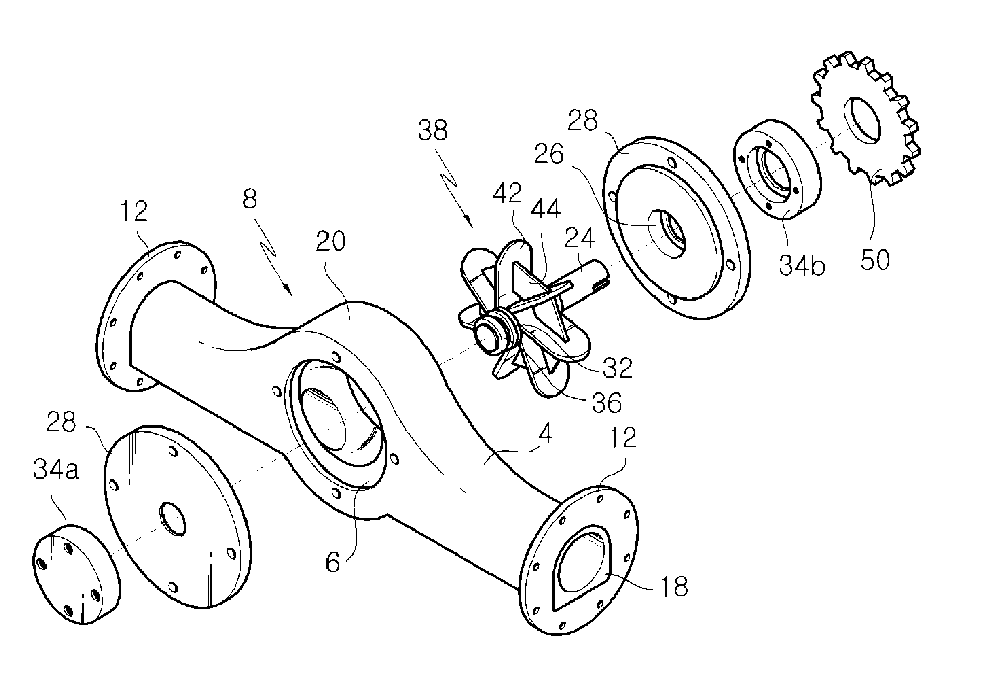
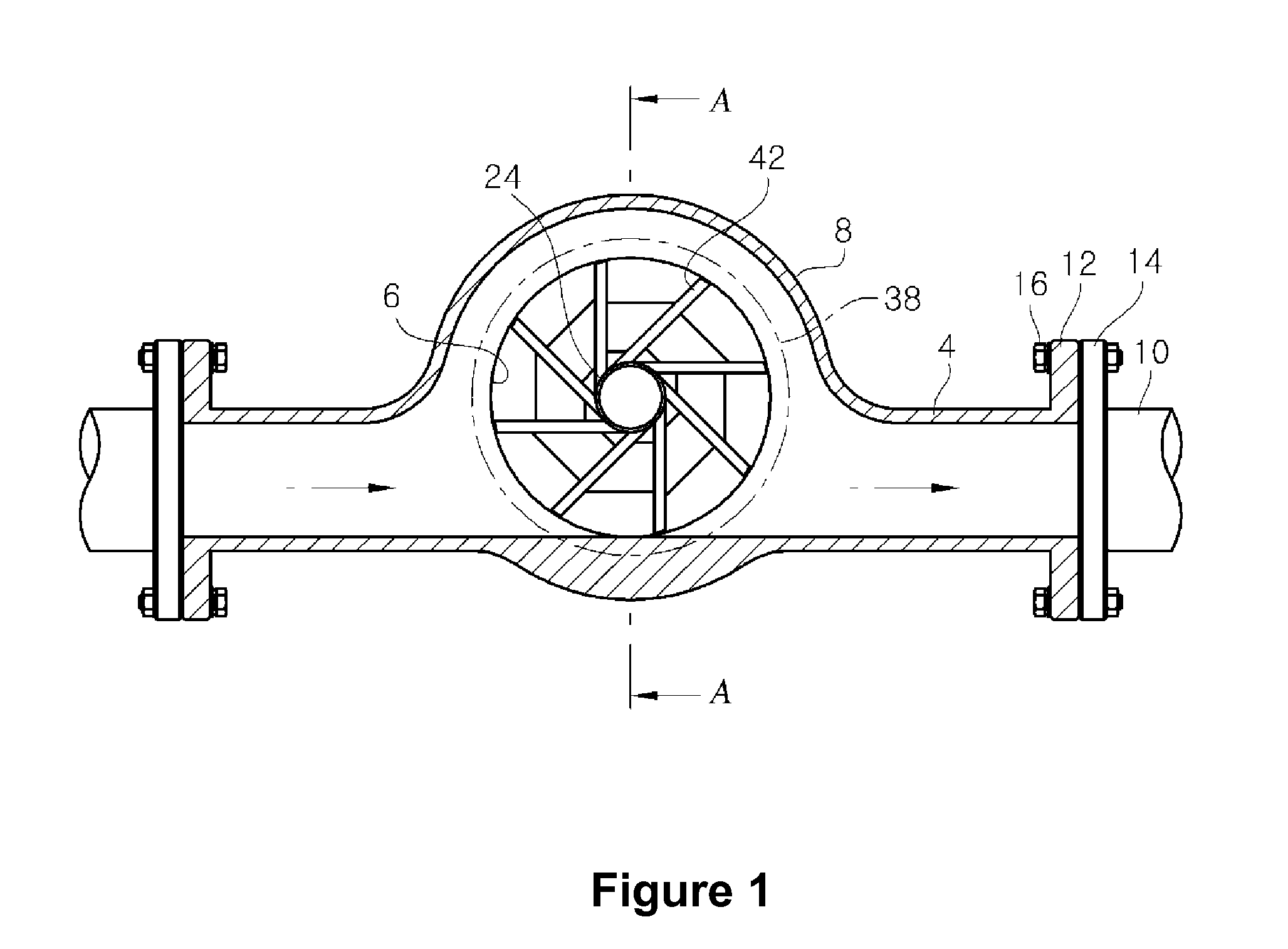
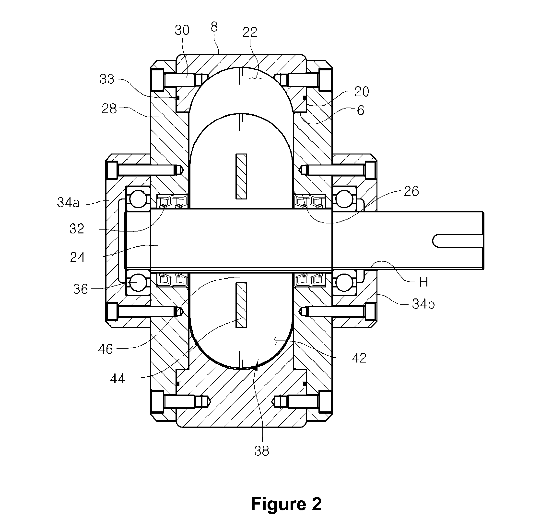
A hydraulic power generation motor includes a tubular body (4) including a pair of coupling flanges (12) formed at opposite ends thereof and an impeller housing (8) formed in an intermediate portion thereof, the coupling flanges (12) being connectable to fluid conduits (10) through which fluid flows. An impeller (38) is rotatably installed within the impeller housing (8) of the tubular body (4), the impeller (38) being designed to be rotated by the fluid and operatively connected to a generator (40) for generating an electric power.

Description

FIELD OF THE INVENTION[0001]The present invention relates to a hydraulic power generation motor for use in generating electric power and, more particularly, to a hydraulic power generation motor that includes an impeller installed in a public or industrial fluid-flowing conduit and rotated by the kinetic energy of fluid flowing through the conduit. The torque of the impeller is used to rotate a generator operatively connected to the hydraulic power generation motor.BACKGROUND ART[0002]In general, electric power is generated by hydraulic power generation, steam power generation or atomic power generation. These power generation methods often pose problems of air pollution, ozone layer destruction and water pollution.[0003]In an effort to develop clean energy or alternative energy, scientists over the world have been studying power generation methods that make use of solar heat, wind power and tidal power. Also developed is a power generation method that utilizes water flowing along a...

Claims


Application Information

Patent Timeline
IPC IPC(8): H02K7/18
CPCF03B13/00F05B2220/602Y02E10/28Y02B10/50Y02E60/17H02K7/1823Y02E10/20Y02E10/30Y02E60/16F03B13/06H02K7/18
Inventor LIM, BYUNG DOO
Owner HWANG MYUNG OK
Learn More