Wireless charging apparatus and wireless charging system

a charging apparatus and wireless charging technology, applied in the direction of sustainable buildings, transportation and packaging, rail devices, etc., can solve the problems of cable deterioration more and more, within the bounds of possibility, etc., and achieve the effect of simple configuration and high efficiency

Inactive Publication Date: 2011-08-04
SONY CORP
View PDF4 Cites 47 Cited by
  • Summary
  • Abstract
  • Description
  • Claims
  • Application Information

AI Technical Summary

Benefits of technology

[0027]By virtue of the present invention, it is possible to transfer power by adoption of a wireless technique without making use of a cable for transferring the power with a high degree of efficiency by making use of a simple configuration which prevents the power transferring mechanism from becoming complicated even if the distance between the power transferring coil serving as the first resonance element and the power receiving coil serving as the third resonance element is long.

Problems solved by technology

In addition, the methods also have a demerit that it is quite within the bounds of possibility that the cable gets deteriorated more and more due to repeated operation for moving the power transferring coil 22.

Method used


Image

  • Wireless charging apparatus and wireless charging system
  • Wireless charging apparatus and wireless charging system
  • Wireless charging apparatus and wireless charging system

Examples


first embodiment

1. First Embodiment

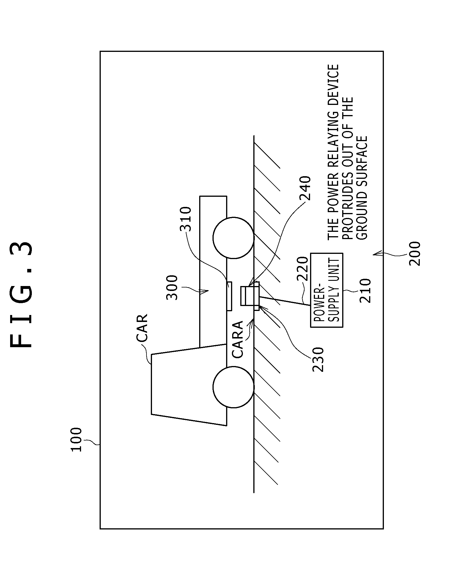
[0056]FIG. 3 is a diagram showing a first typical configuration of a wireless electrical charging system 100 according to a first embodiment of the present invention.

[0057]FIG. 4 is a diagram showing equivalent blocks of the wireless electrical charging system 100 according to the first embodiment.

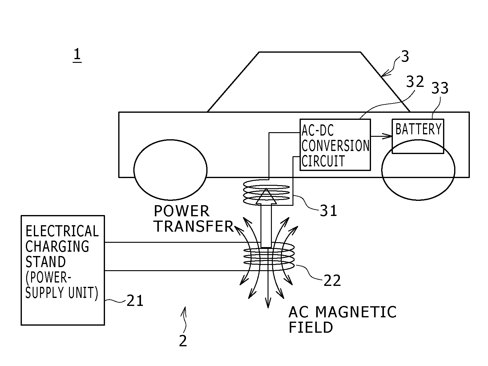
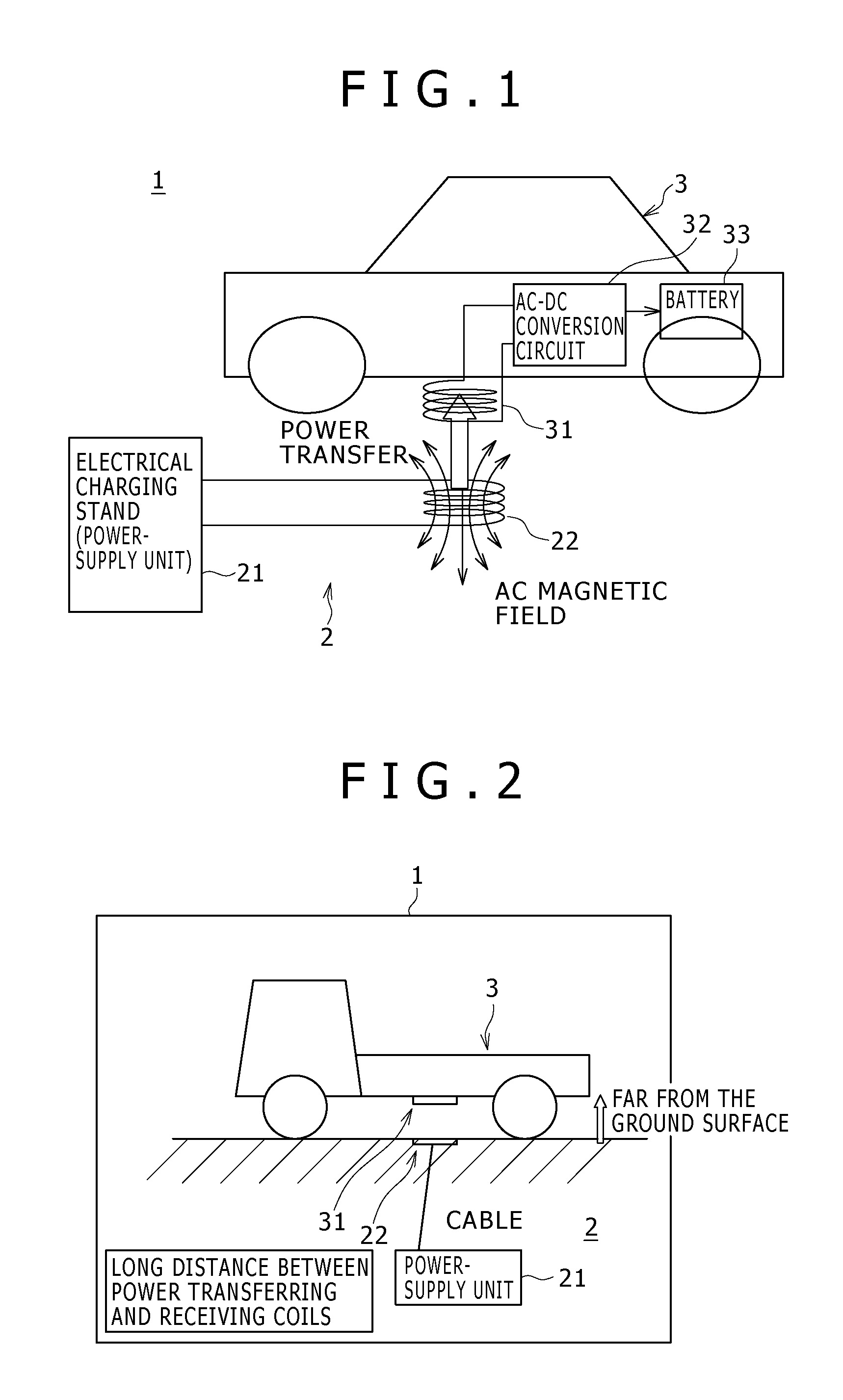
[0058]As shown in the figures, the wireless electrical charging system 100 includes a wireless electrical charging apparatus 200 also referred to as a wireless electrical charging stand and a power receiving apparatus 300 which is typically mounted on an electric car.

[0059]The wireless electrical charging apparatus 200 employs a power-supply unit 210, a power-supply cable 220, a power transferring device 230 and a power relaying device 240.

[0060]The power-supply unit 210 includes an AC power generator 211 for generating high-frequency AC power to be transferred to the power receiving apparatus 300 by adoption of a wireless power transferring technique.

[0061]The AC power ...

second embodiment

2. Second Embodiment

[0162]FIG. 20 is a diagram showing a second typical configuration of a wireless electrical charging system 100E according to a second embodiment of the present invention.

[0163]The wireless electrical charging system 100E according to the second embodiment is different from the wireless electrical charging systems 100 to 100D according to the first embodiment in that, in the case of the wireless electrical charging system 100E according to the second embodiment, a power relaying device 370 is included in a power receiving apparatus 300E mounted on the vehicle CAR.

[0164]In order to carry out an operation to electrically charge the power receiving apparatus 300E for example, a charge switch of the power receiving apparatus 300E is typically pressed. When the charge switch is pressed, the power relaying device 370 is automatically protruded out to a position between the power-supplying-side resonance coil 232 employed in the power transferring device 230 and the powe...

third embodiment

3. Third Embodiment

[0166]FIG. 21 is a diagram showing a third typical configuration of a wireless electrical charging system 100F according to a third embodiment of the present invention.

[0167]The wireless electrical charging system 100F according to the third embodiment is different from the wireless electrical charging systems 100 to 100D according to the first embodiment and the wireless electrical charging system 100E according to the second embodiment in that, in the case of the wireless electrical charging system 100F according to the third embodiment, a plurality of power receiving devices 310 are mounted on the vehicle CAR. In the case of the typical configuration of the wireless electrical charging system 100F according to the third embodiment, power receiving devices 310-1 to 310-4 are mounted on the vehicle CAR.

[0168]In this typical configuration, instead of installing the power receiving devices 310 at the bottom of the vehicle CAR, the power receiving device 310-1 is mo...


PUM


Abstract

Disclosed herein is a wireless electrical charging apparatus, including: a power-supply unit configured to generate power to be transferred to a power receiving apparatus; a power transferring device configured to transfer power generated by the power-supply unit to the power receiving apparatus; a power relaying device capable of relaying power transferred by the power transferring device to the power receiving apparatus; and a power-relaying-device moving mechanism section configured to move the power relaying device.

Description

BACKGROUND OF THE INVENTION[0001]1. Field of the Invention[0002]The present invention relates to a wireless electrical charging apparatus adopting a noncontact power supplying method allowing power to be transferred to a battery employed in an electric car or the like as power to be supplied to the battery, and relates to a wireless electrical charging system.[0003]2. Description of the Related Art[0004]Typically, a battery employed in an electric car is electrically charged by adoption of a general method by which a cable of an electrical charging stand is plugged into the battery in order to electrically charge the battery.[0005]However, the amount of transferred power is large, requiring a thick and heavy cable to be plugged into the battery and connected to the battery. In addition, if the operation to electrically charge the battery is carried out outdoors, rainwater or the like makes the operation dangerous in some cases.[0006]In order to solve the problem described above, the...

Claims


Application Information

Patent Timeline
Patent Type & Authority Applications(United States)
IPC IPC(8): H02J7/00B60L5/00B60M7/00
CPCY02T90/16Y02B60/50H02J7/00H02J50/12H02J50/90H02J50/80H02J50/40H02J50/50B60L53/126
Inventor MURAYAMA, YUJI
Owner SONY CORP
Why Eureka
Try Eureka