Dual-band antenna

Active Publication Date: 2011-08-04
AMBIT MICROSYSTEMS (SHANGHAI) LTD
View PDF7 Cites 1 Cited by
  • Summary
  • Abstract
  • Description
  • Claims
  • Application Information

AI Technical Summary

Problems solved by technology

However, antennas are prone to deformation if squeezed or impacted during installation and usage.
After deformation,

Method used


Image

  • Dual-band antenna
  • Dual-band antenna
  • Dual-band antenna

Examples


Embodiment Construction

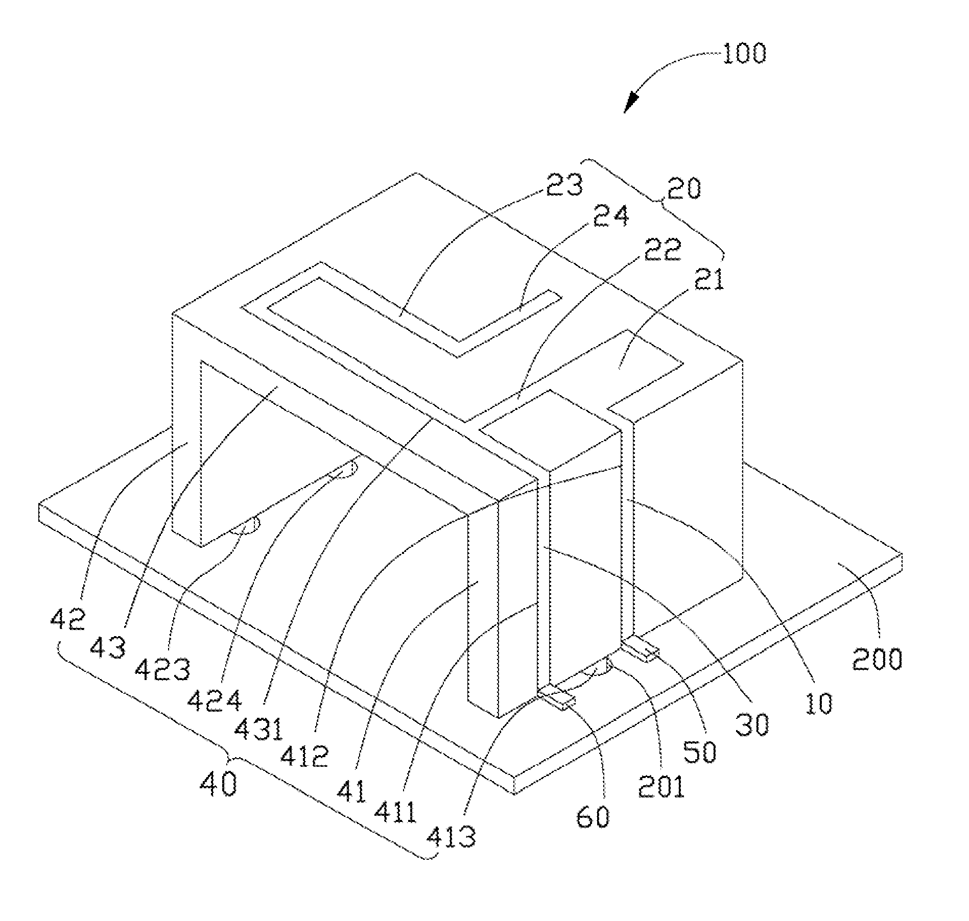
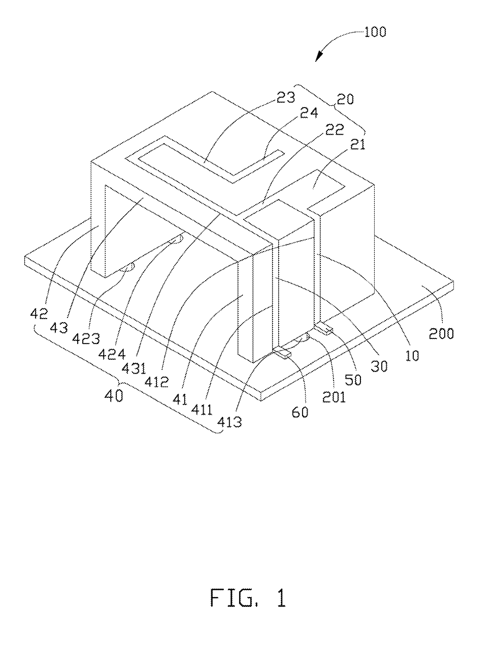
[0008]Referring to FIG. 1, a schematic diagram of an embodiment of a dual-band antenna 100 as disclosed is shown. The dual-band antenna 100 is disposed on a substrate 200, and comprises a feeding portion 10, a radiating portion 20, a grounding portion 30, an insulating support portion 40, a matching connector 50, and a metal connector 60.

[0009]The insulating support portion 40 is made of a dielectric, such as plastic. In one embodiment, the insulating support portion 40 comprises a first support wall 41, a second support wall 42, and a third support wall 43. The first support wall 41 and the second support wall 42 are perpendicularly connected to the substrate 200. The third support wall 43 is parallel to the substrate 200, and perpendicularly connected to the first support wall 41 and the second support wall 42. In one embodiment, a shape and a location of the second support wall 42 may be adjustable.

[0010]The feeding portion 10 feeds electromagnetic signals. In one embodiment, the...


PUM


Abstract

A dual-band antenna includes a feeding portion, a radiating portion, a grounding portion, and an insulating support portion. The insulating support portion includes a first support wall, a second support wall, and a third support wall. The third support wall is parallel to the substrate, and perpendicularly connected to the first support wall and the second support wall, to position the radiating portion.

Description

BACKGROUND[0001]1. Technical Field[0002]Embodiments of the present disclosure relate to antennas, and especially to a dual-band antenna.[0003]2. Description of Related Art[0004]Antennas are one important component of wireless communication devices, where performance and size of the antennas affect quality of the wireless communications devices. However, antennas are prone to deformation if squeezed or impacted during installation and usage. After deformation, radiation patterns of the antennas may be changed and / or unstable, and lead to adverse effects on signal reception.[0005]It is therefore desirable to provide a new antenna which can overcome the above mentioned problems.BRIEF DESCRIPTION OF THE DRAWINGS[0006]FIG. 1 is a schematic diagram of an embodiment of a dual-band antenna according to the present disclosure; and[0007]FIG. 2 is a graph showing an exemplary return loss of the dual-band antenna of FIG. 1.DETAILED DESCRIPTION[0008]Referring to FIG. 1, a schematic diagram of an...

Claims


Application Information

Patent Timeline
IPC IPC(8): H01Q1/38H01Q13/10
CPCH01Q13/10H01Q1/38H01Q5/371H01Q9/42H01Q9/0421
Inventor LI, PINGZHANG, CHONGCHUNG, CHO-JU
Owner AMBIT MICROSYSTEMS (SHANGHAI) LTD
Why Eureka
Try Eureka