
Light-reflecting strip and liquid crystal display device including same

a technology of liquid crystal display device and light-reflecting strip, which is applied in the direction of lighting device details, lighting and heating apparatus, instruments, etc., can solve the problems of reducing the efficiency of heat dissipation, reducing the number of light sources used, and reducing the electric power consumption and heat generation.

Active Publication Date: 2011-08-04
TAIWAN PAIHO LTD
View PDF4 Cites 0 Cited by
  • Summary
  • Abstract
  • Description
  • Claims
  • Application Information

AI Technical Summary

Benefits of technology

[0004]In view of the above-mentioned disadvantages / problems associated with the existing liquid crystal display, one object of the present invention is to provide a light-reflecting strip for a back-light module of a liquid crystal display so as to reduce the number of light sources used in the back-light module and to achieve the goal of reducing the electric power consumption and heat generation. Another object of the present invention is to provide a liquid crystal display device that includes the light-reflecting strip.

Problems solved by technology

However, these back light sources not only consume electric power of the electronic apparatus in which they are installed but also produce a substantive amount of heat.
Additionally, under the trend of lighter, thinner and smaller of the portable electronic apparatuses, electric components, including the liquid crystal display, are installed in a more limited space in a more compact manner and this makes the heat dissipation problem becomes an issue that needs to be effectively solved.

Method used


Image

  • Light-reflecting strip and liquid crystal display device including same
  • Light-reflecting strip and liquid crystal display device including same
  • Light-reflecting strip and liquid crystal display device including same

Examples


Embodiment Construction

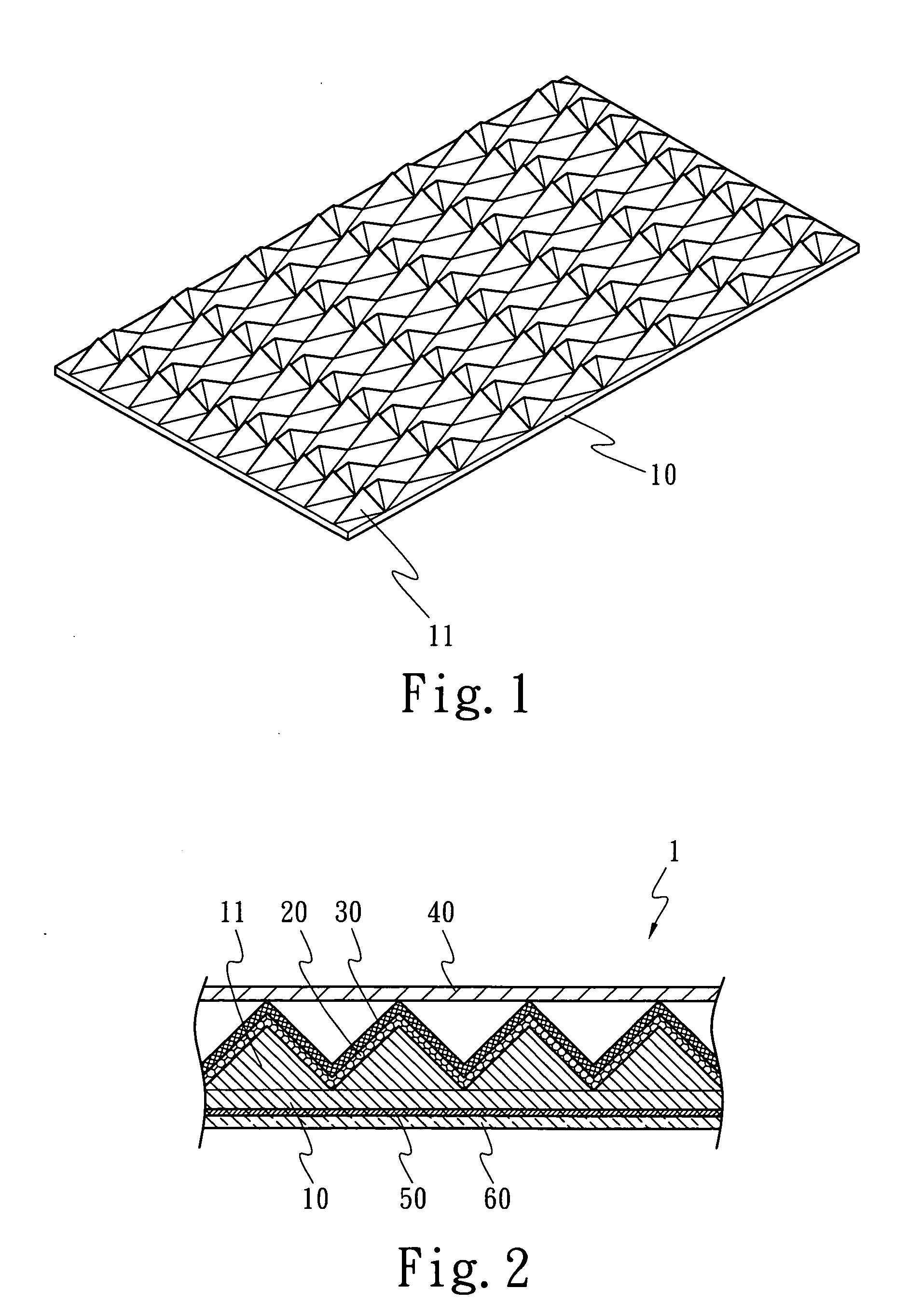
[0020]Referring now to FIGS. 1 and 2 to describe a light-reflecting strip for a liquid crystal display according to a preferred embodiment of the present invention. FIG. 1 is a schematic perspective view illustrating a light-reflecting substrate 10 used in a light-reflecting strip according to one embodiment of the present invention. The light-reflecting substrate 10 has a configuration surface on which a matrix of protruded pyramid embossing patterns 11 are formed. Although in this embodiment a surface configuration having a matrix of protruded pyramid embossing patterns is used as a surface configuration of the light-reflecting substrate, other surface configurations, such as a semi-spherical configuration, may be adapted as the surface configuration of the light-reflecting substrate of the light-reflecting strip of the present invention.

[0021]FIG. 2 is a schematic cross-sectional view of a light-reflecting strip 1 according to a preferred embodiment of the present invention. As s...


PUM

PropertyMeasurementUnit
transmittanceaaaaaaaaaa
reflectivityaaaaaaaaaa
electric poweraaaaaaaaaa

Abstract

One aspect of the present invention provides a light-reflecting strip for a liquid crystal display device. The light-reflecting strip includes a light-reflecting substrate having a configuration surface and a smooth surface; a light-reflecting base layer coated on the configuration surface; a reflecting layer deposited on the light-reflecting base layer by evaporation deposition; a high transmittance colorant layer printed on the reflecting layer by means of a screen printing with a screen having a mesh number greater than 300; an adhesive layer applied on the smooth surface of the light-reflecting substrate; and a release paper detachably adhered to the adhesive layer. Another aspect of the present invention provides a liquid crystal display device including the light-reflecting strip.

Description

FIELD OF THE INVENTION[0001]The present invention relates generally to a high reflectivity light-reflecting strip, especially a light-reflecting strip used as a passive light source of a liquid crystal display device, and a liquid crystal display device including the high reflectivity light-reflecting strip.BACKGROUND OF THE INVENTION[0002]A flap panel display, such as a liquid crystal display (LCD), is widely used in various electronic apparatuses as a device to display information or images. When displaying information or images, the LCD requires a back light source, such as cold cathode tubes or light-emitted diodes (LEDS), to display the information or images. However, these back light sources not only consume electric power of the electronic apparatus in which they are installed but also produce a substantive amount of heat. For hand-held or mobile electronic apparatuses, such as notebook type personal computers or cell phones, the electric power is provided by batteries. There...

Claims


Application Information

Patent Timeline
Patent Type & Authority Applications(United States)
IPC IPC(8): G02F1/1335F21V7/22
CPCG02B5/124G02F1/133605G02B6/0053G02B6/0031
Inventor CHENG, ALLEN
Owner TAIWAN PAIHO LTD
Features
  • Generate Ideas
  • Intellectual Property
  • Life Sciences
  • Materials
  • Tech Scout
  • Unparalleled Data Quality
  • Higher Quality Content
  • 60% Fewer Hallucinations
Learn More