Interface control system and interface control method

a control system and interface technology, applied in the field of interface control system, can solve the problems of excessive complexity of network configuration itself and heavy load on the control unit of the communication unit, and achieve the effect of flexible control of flow

Inactive Publication Date: 2011-08-04
NEC CORP
View PDF21 Cites 134 Cited by
  • Summary
  • Abstract
  • Description
  • Claims
  • Application Information

AI Technical Summary

Benefits of technology

[0019]According to the present invention, a flow can be con

Problems solved by technology

As the result of adoption of broadband communication and ALL IP (Internet Protocol) in recent years, it is necessary to perform complicated manipulation and many processes for network, load imposed on a control unit of the communication unit

Method used


Image

  • Interface control system and interface control method
  • Interface control system and interface control method
  • Interface control system and interface control method

Examples


first exemplary embodiment

(Configuration of Existing Network Equipment)

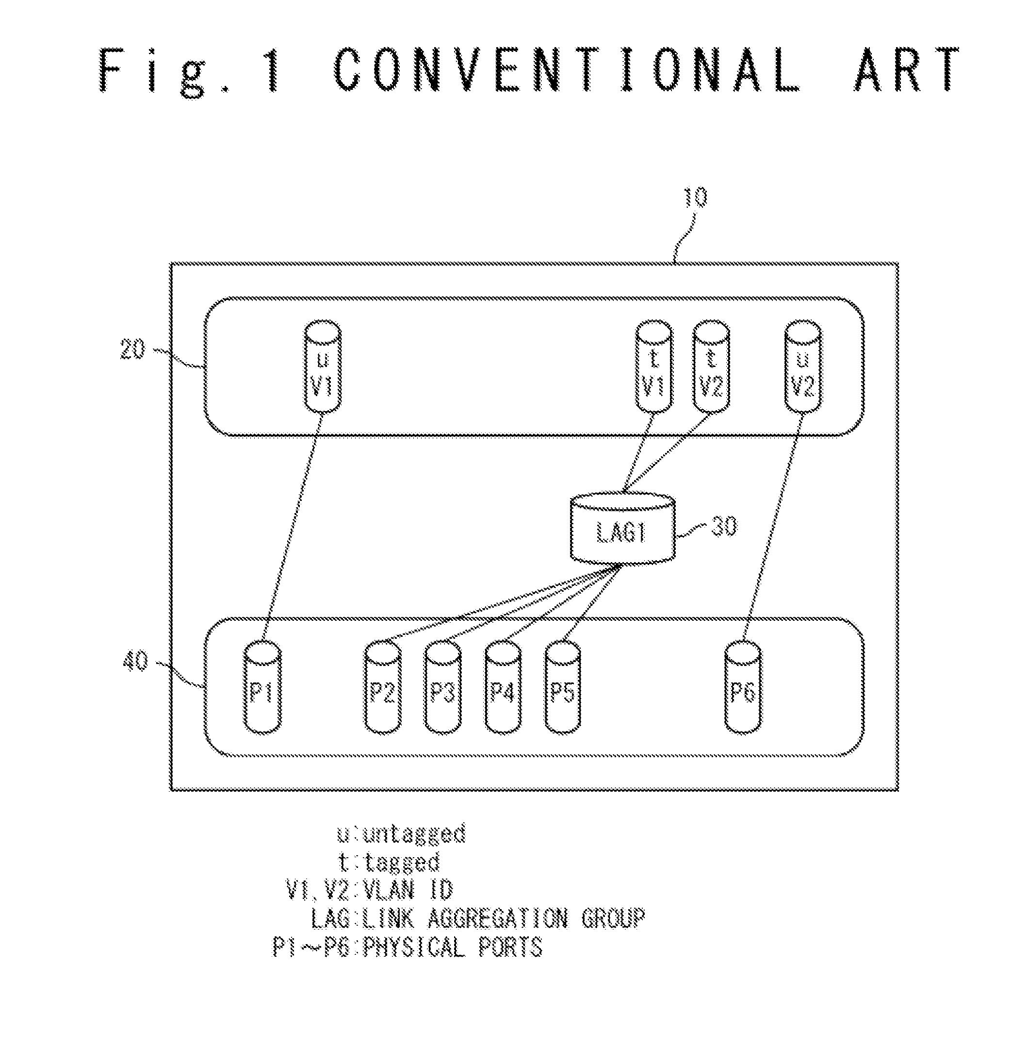
[0029]FIG. 1 shows a configuration of existing network equipment 10 which attains an open flow (OpenFlow) function.

[0030]The existing network equipment 10 has a VLAN (Virtual Local Area Network) interface 20, a link aggregation group interface 30 and physical port group 40.

[0031]The VLAN interface 20 is a logical interface for VLAN groups. Here, the VLAN interface 20 contains a VLAN “V1” and a VLAN “V2”. The VLAN “V1” and the VLAN “V2” are VLAN numbers (VLAN IDs), and are the VLAN groups corresponding to the VLAN numbers.

[0032]The link aggregation group interface 30 is a logical interface of the link aggregation group. Here, the link aggregation group interface 30 functions as a logical interface of a link aggregation group “LAG1”.

[0033]The physical port group 40 is a physical interface of the existing network equipment 10. The physical port group 40 contains physical ports “P1” to “P6”. The physical port “P1” belongs to the VLAN “V1” as ...

second exemplary embodiment

[0071]Next, referring to the drawings, a second exemplary embodiment of the present invention will be described.

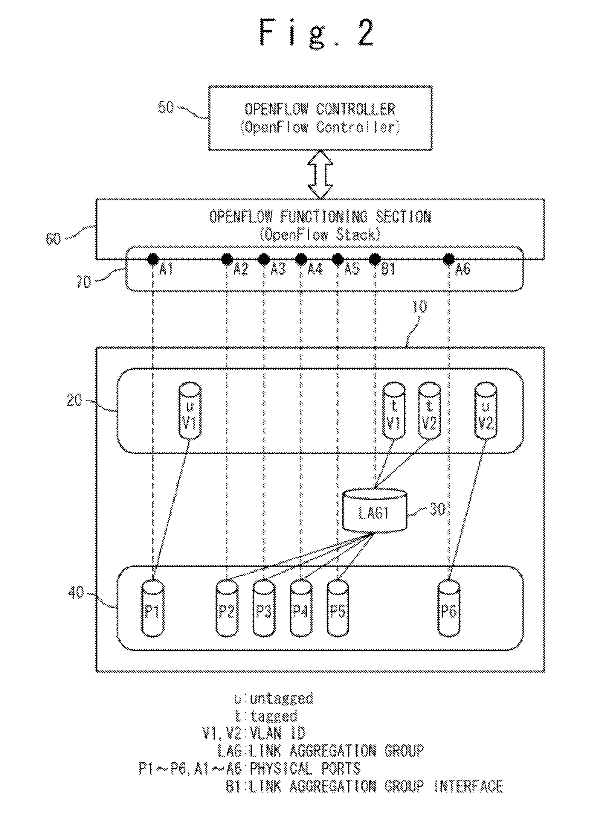
[0072]In the present exemplary embodiment, in addition to the link aggregation group interface, a VLAN interface is added as a management object. The link aggregation group and the VLAN group are virtual groups (logical groups).

[0073]In FIG. 7, a VLAN interface 20 has a VLAN “V1”. The physical port group 40 includes the physical ports “P1” to “P6”. An open flow interface (OpenFlow Interface) 70 has the physical ports “A1” to “A6”, a link aggregation group interface “B1” and a VLAN interface “C1”.

[0074]Here, the physical ports “P2” to “P4” belongs to the VLAN “V1”. That is, the physical ports “P2” to “P4” configure the VLAN interface 20. The physical ports “P5” and “P6” belong to the link aggregation group “LAG1”. That is, the physical ports “P5” and “P6” configure the link aggregation group interface 30.

[0075]The physical ports “A1” to “A6” correspond to the physical ports...


PUM


Abstract

An interface control system of network equipment, includes: a logical interface which is an interface of a logical group; physical ports which belong to the logical group; and an interface control section configured to incorporate the logical interface and the physical ports as management objects into a management interface when validation of a predetermined function has been performed to each of the logical interface and the physical ports.

Description

INCORPORATION BY REFERENCE[0001]This patent application claims a priority on convention based on Japanese Patent Application No. 2010-019963 filed on Feb. 1, 2010. The disclosure thereof is incorporated herein by reference.TECHNICAL FIELD[0002]The present invention is related to an interface control system, and particularly, to an interface control system for network units in an open flow (OpenFlow).BACKGROUND ART[0003]Conventionally, unit management and communication process are performed in a communication unit. As the result of adoption of broadband communication and ALL IP (Internet Protocol) in recent years, it is necessary to perform complicated manipulation and many processes for network, load imposed on a control unit of the communication unit has become heavy. It should be noted that ALL IP means an environment that all the units are connected with an IP network.[0004]In this way, the load on the unit has become heavy with rapid development of a network infrastructure, so t...

Claims


Application Information

Patent Timeline
IPC IPC(8): H04L1/24G06F21/20H04L12/46H04L45/42H04L47/41
CPCH04L1/24H04L41/00
Inventor SAITO, SHUICHI
Owner NEC CORP
Why Eureka
Try Eureka