
Method and magnetic resonance device to determine a background phase curve

Active Publication Date: 2011-08-04
SIEMENS HEALTHCARE GMBH
View PDF8 Cites 2 Cited by
  • Summary
  • Abstract
  • Description
  • Claims
  • Application Information

AI Technical Summary

Benefits of technology

[0009]An object of the present invention is based to provide an improved method and an improved device with which the curve of the background phase can be determined. In particular, an object of the invention is to specify a method and a device that allow a reliable determination of the background phase curve without repetition of the measurement on a sample body.

Problems solved by technology

Background phase effects can impair the precision of such measurements since the background phase of the velocity-dependent phase information is overlaid.
However, such a repetition is normally complicated.
However, since such a table formation can typically take place only for a specific number of sets of measurement parameters, it would be necessary to either correspondingly limit the parameter space that can be used in the measurement or to interpolate between the table values.
Time variations of the MR device can lead to the situation that the quality of the correction decreases over time, even under consideration of these limitations.
The method described by J. W. Lankhaar et al. thus can not always be implemented for slices in which only a small number of stationary points are present, or cannot always be implemented with acceptable precision.

Method used


Image

  • Method and magnetic resonance device to determine a background phase curve
  • Method and magnetic resonance device to determine a background phase curve
  • Method and magnetic resonance device to determine a background phase curve

Examples


Embodiment Construction

[0048]The features of the exemplary embodiments described in the following can be combined with one another insofar as this is not explicitly indicated otherwise.

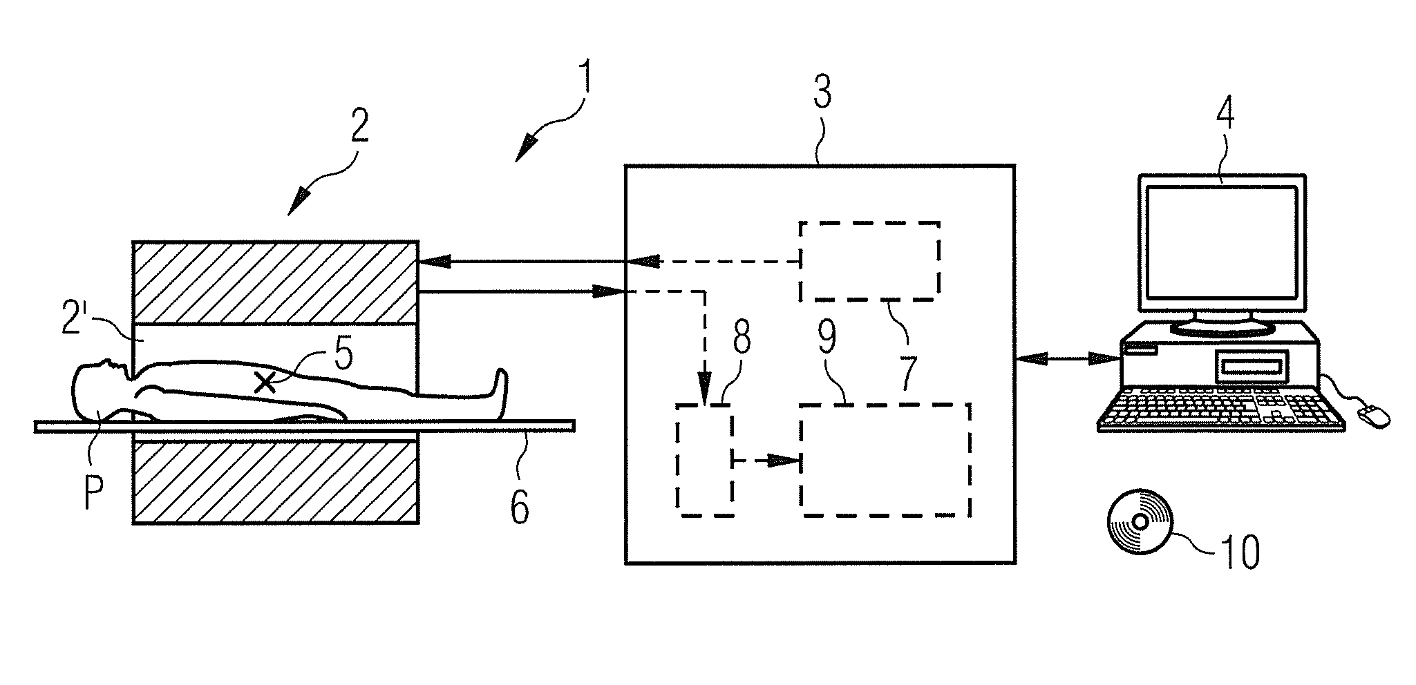
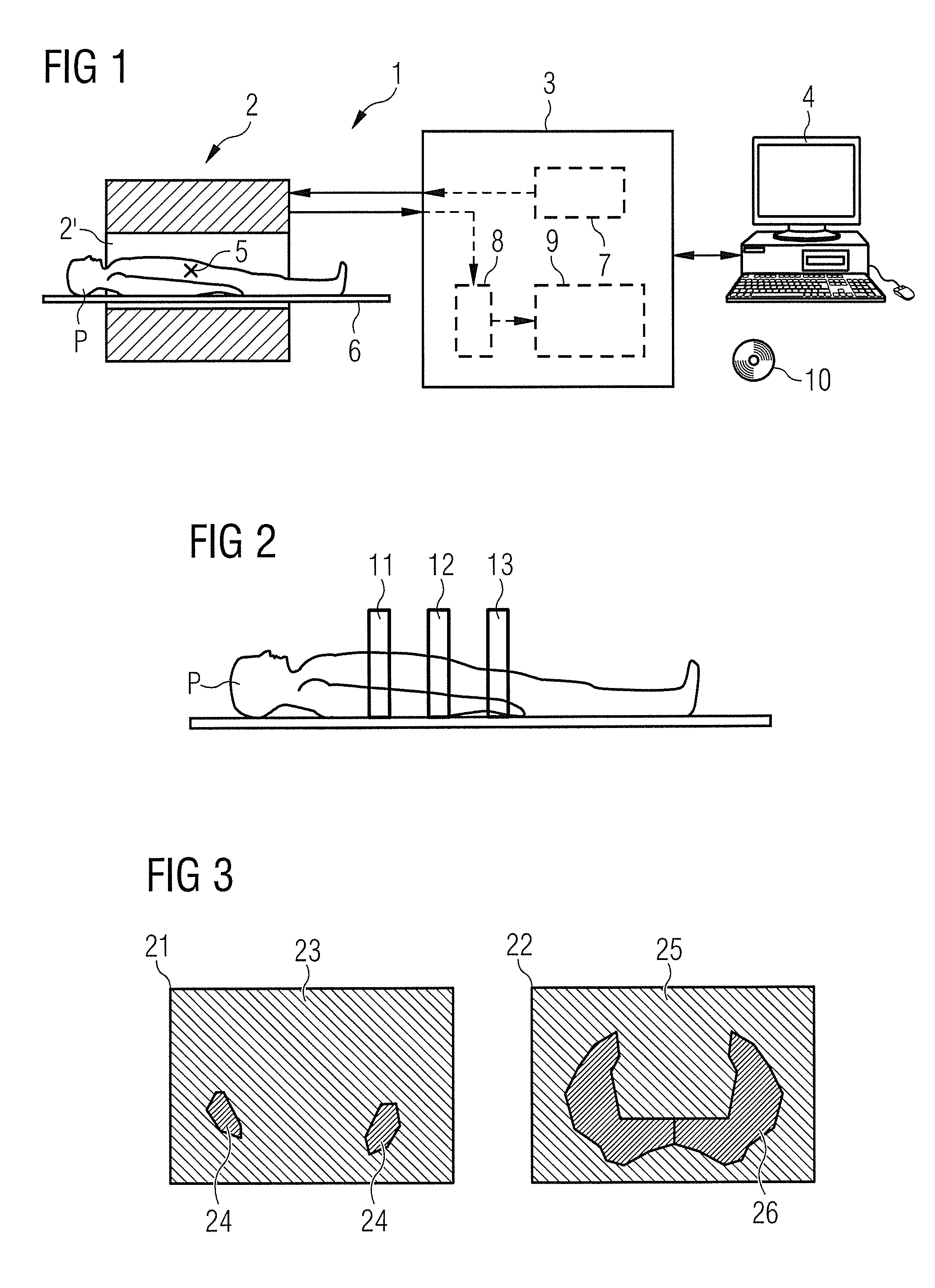
[0049]FIG. 1 is a schematic representation of a magnetic resonance (MR) device 1 according to one exemplary embodiment. The MR device 1 has a scanner (data acquisition device) 2, a control device 3 and an evaluation computer 4. The scanner 2 has one or more coil arrangements with which the magnetic fields required for a data acquisition can be generated in a measurement space 2′. The isocenter of the BO field is designated 5. The scanner 2 can include gradient coils with which gradient fields for a phase-sensitive flow measurement or an angiography can be activated in order to achieve a phase coding of velocities. The scanner 2 can be configured so that the data acquisition that is required for a phase-sensitive flow measurement or angiography can be implemented by shifting time-variable, in particular bipolar gradient fiel...


PUM


Abstract

In a magnetic resonance (MR) device and method to determine a background phase curve in MR image data, in first MR image data and in second MR image data that respectively represent different segments (for example different slices) of an examination subject, first and second pixels are identified that represent essentially stationary tissue, and the associated phase values are determined. Phase correction values for the first MR image data are determined depending on the phase values determined for the first and second pixels that represent essentially stationary tissue.

Description

BACKGROUND OF THE INVENTION[0001]1. Field of the Invention[0002]The present invention concerns a method to determine a background phase curve in magnetic resonance (MR) image data and a magnetic resonance device that implements such a method. The invention in particular concerns such a method and such a device with which a background phase curve can be determined in a phase-sensitive flow measurement or in an angiography procedure.[0003]2. Description of the Prior Art[0004]Different methods that allow the determination of flow or movement velocities of tissue using imaging MR techniques are known and described, for example by Heinz Morneburg (Ed.), “Bildgebende Systeme für die medizinische Diagnostik” [“Imaging Systems for Medical Diagnostics”], 3rd Edition, 1995, Publicis MCD Verlag, Erlangen. In order to acquire velocity information, for example, magnetic field gradients can be shifted that cause a velocity-dependent contribution to the phase of the spins or, respectively, the mag...

Claims


Application Information

Patent Timeline
IPC IPC(8): G06K9/00G01R33/48
CPCG01R33/56518G01R33/56316
Inventor GREISER, ANDREASLITTMANN, ARNE
Owner SIEMENS HEALTHCARE GMBH
Features
  • Generate Ideas
  • Intellectual Property
  • Life Sciences
  • Materials
  • Tech Scout
  • Unparalleled Data Quality
  • Higher Quality Content
  • 60% Fewer Hallucinations
Learn More