
Operator-Controlled Scanning Laser Procedure Designed for Large-Area Epithelium Removal

a laser and operator-controlled technology, applied in laser surgery, medical science, surgery, etc., can solve the problems of affecting and affecting the accuracy of laser eye surgery. , to achieve the effect of improving the accuracy and efficacy of laser eye surgery, improving the removal of the epithelium, and improving the accuracy of laser eye surgery

Inactive Publication Date: 2011-08-04
AMO MFG USA INC
View PDF25 Cites 0 Cited by
  • Summary
  • Abstract
  • Description
  • Claims
  • Application Information

AI Technical Summary

Benefits of technology

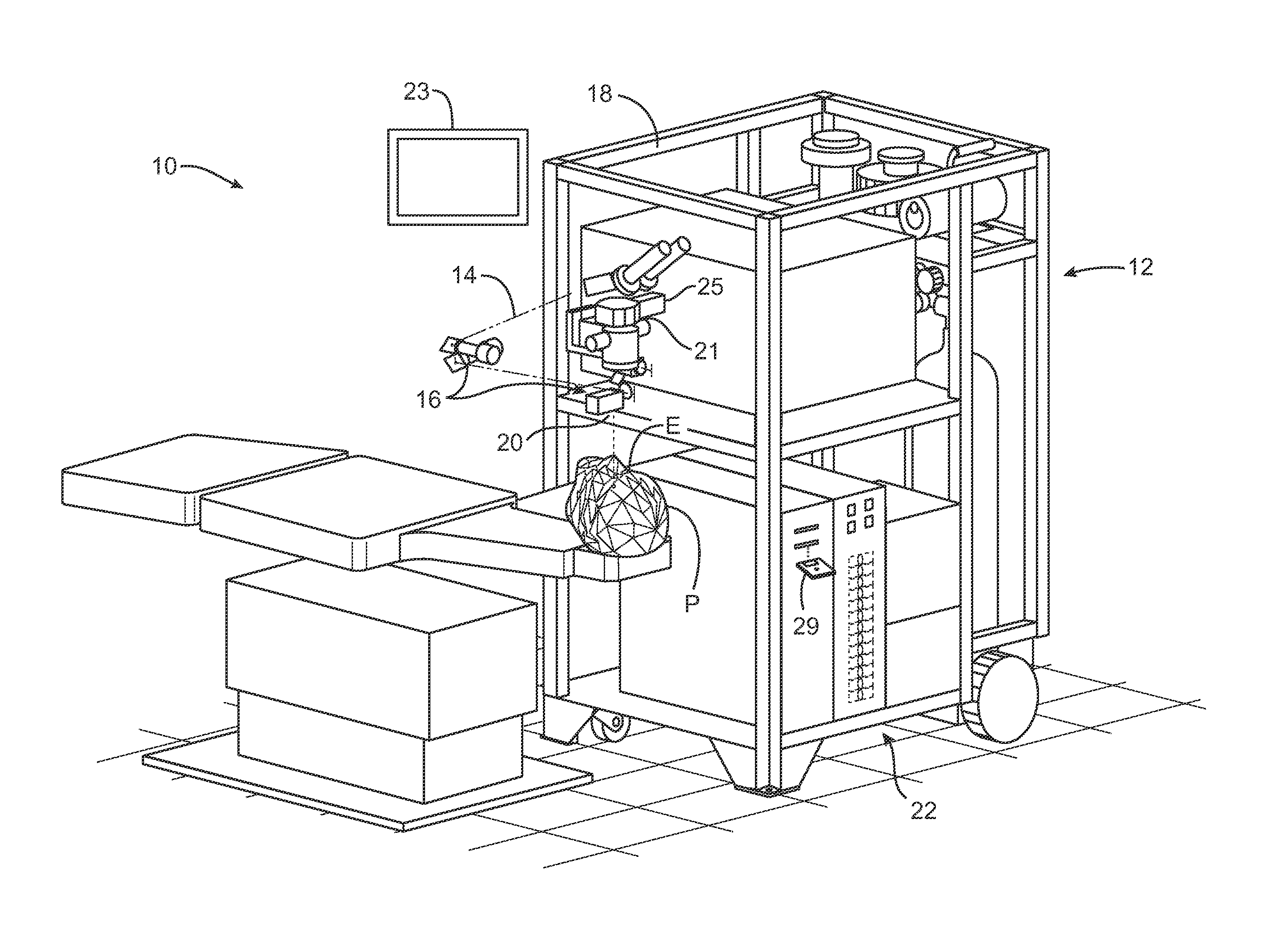
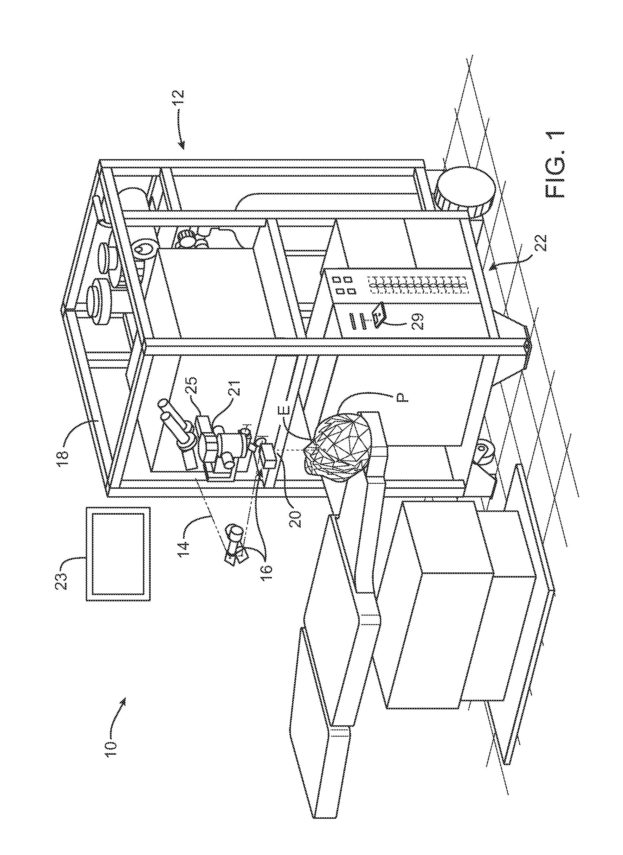
[0009]Embodiments of the present invention provide improved devices, systems, and methods for laser treatment, for example laser treatment of eyes. More specifically, embodiments of the present invention can enhance the accuracy and efficacy of laser eye surgical procedures with improved removal of the epithelium, for example the corneal epithelium. This improved removal of the corneal epithelium can improve refractive surgical procedures, for example PRK, and can be useful for the therapeutic removal of corneal haze. While the system and methods of the present invention are described primarily in the context of a laser eye surgery system for treating the cornea of the eye, it should be understood that the techniques described herein may be adapted for use in many additional ablation procedures.
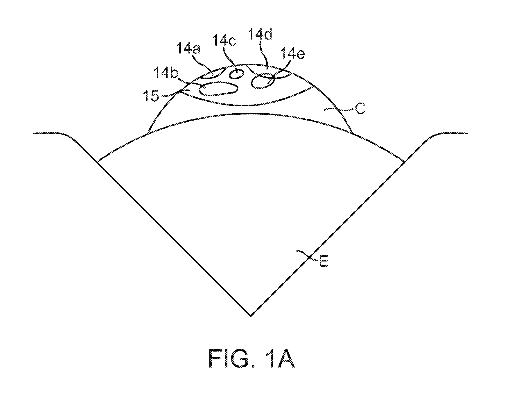
[0010]Many embodiments use a scanning laser beam that ablates an area larger than the beam and induces fluorescence of the ablated tissue layer, for example the corneal epithelium. A sequence of pulses of the beam is arranged to enhance optical feedback based on the tissue fluorescence so that areas of the epithelium larger than the beam can be ablated and tissue penetration detected. The size and position of the pulse sequence can be arranged to overlap at least some the scanning pulses on a region smaller than the ablation, for example a central region, so that penetration of the epithelium can be detected by viewing the region. Hence, enhanced optical feedback encompasses scanning pulses with a size and position arranged to ablate an area larger than the beam and overlap the pulses on a region, or portion, of the ablated area so that penetration of the epithelium can be detected by viewing the region. In many embodiments an operator may view the region and stop the ablation in response to the enhanced optical feedback, and in some embodiments and energy detector, such as a CCD camera, may view the region ablated pulse sequence arranged to enhance optical feedback.
[0012]In many embodiments, the pulse sequence is sorted to enhance the optical feedback. Stromal tissue can be ablated with an optical correction in response the penetration of the epithelial layer.
[0015]In another aspect, embodiments provide a method for removing an epithelial layer disposed over a stromal layer in a cornea. A region of the epithelial layer is irradiated with laser beam pulses of ablative radiation. The ablative radiation is scanned to vary the location of the beam pulses within the region. The beam is adjusted to at least one smaller beam size and at least one larger beam size while the beam is pulsed and scanned over the region in accordance with a pulse sequence arranged to enhance optical feedback. The penetration of the epithelial layer is detected based on tissue fluorescence from the larger sized beam.
[0030]In many embodiments, the computer is configured to sort the pulse sequence to enhance the optical feedback.

Problems solved by technology

Although these mechanical methods of epithelial removal have been successful clinically, mechanical removal of the epithelium takes time and can be perceived by the patients as invasive because the surgeon will touch the front surface of the eye with surgical instruments.
Even though topical anesthesia is often applied to the cornea so that the patient cannot feel the surgeon touching his or her cornea, the patient can become nervous while the surgeon touches the front surface of the eye with the instruments, possibly delaying the procedure.

Method used


Image

  • Operator-Controlled Scanning Laser Procedure Designed for Large-Area Epithelium Removal
  • Operator-Controlled Scanning Laser Procedure Designed for Large-Area Epithelium Removal
  • Operator-Controlled Scanning Laser Procedure Designed for Large-Area Epithelium Removal

Examples


Embodiment Construction

[0055]The present invention is particularly useful for enhancing the accuracy and efficacy of laser eye surgical procedures, such as photorefractive keratectomy (PRK), phototherapeutic keratectomy (PTK), and the like. Preferably, the present invention can provide enhanced optical accuracy of refractive procedures and improved patient comfort during the procedure by improving removal of the corneal epithelium. Hence, while the system and methods of the present invention are described primarily in the context of a laser eye surgery system for treating a cornea of the eye, it should be understood the techniques of the present invention may be adapted for use in alternative ablation procedures.

[0056]The techniques of the present invention can be readily adapted for use with existing laser systems. By providing a more rapid (and hence, may be less prone to error) methodology for correcting optical errors of an eye, the present invention facilitates sculpting of the cornea so that treated...


PUM


Abstract

Systems and methods for removing an epithelial layer disposed over a stromal layer in a cornea irradiate a region of the epithelial layer with a pulsed beam of ablative radiation. The ablative radiation is scanned to vary the location of the beam within the region in accordance with a pulse sequence. The pulse sequence is arranged to enhance optical feedback based on a tissue fluorescence of the epithelial layer. The penetration of the epithelial layer is detected in response to the optical feedback. The use of scanning with the pulse sequence arranged to enhance optical feedback allows large areas of the epithelium to be ablated such that an operator can detect penetration of the epithelial layer.

Description

CROSS-REFERENCES TO RELATED APPLICATIONS[0001]This application is a Continuation of U.S. application Ser. No. 11 / 937,760 filed Nov. 9, 2007 (Allowed), which application claims the benefit under 35 USC 119(e) of U.S. Provisional Application No. 60 / 865,342 filed Nov. 10, 2006; the full disclosures, each of which are incorporated herein by reference in their entirety for all purposes.BACKGROUND OF THE INVENTION[0002]The present invention is generally related to correcting optical errors of light refracted by eyes. In exemplary embodiments, the invention provides devices, systems, and methods for correction of optical errors of eyes, and is particularly well suited for the treatment of eyes during photorefractive keratectomy (PRK) and the like.[0003]Known laser eye surgery procedures generally employ an ultraviolet or infrared laser to remove a microscopic layer of stromal tissue from the cornea of the eye. The laser typically removes a selected shape of the corneal tissue, often to cor...

Claims


Application Information

Patent Timeline
Patent Type & Authority Applications(United States)
IPC IPC(8): A61F9/008
CPCA61B2017/00057A61F9/008A61F9/00806A61F9/00817A61F2009/00897A61F2009/00848A61F2009/00872A61F2009/0088A61F2009/00882A61F2009/00844
Inventor ARNOLDUSSEN, MARK E.WONG, JONATHANLOGAN, BENJAMIN A.
Owner AMO MFG USA INC
Learn More