
Electrosurgical device with vacuum port

a vacuum port and electrosurgical technology, applied in the field of smoke evacuation, can solve the problems of thermal necrosis in adjacent cells, cell membrane burst, increased cell pressure inside the cell,

Active Publication Date: 2011-08-04
BUFFALO FILTER
View PDF14 Cites 56 Cited by
  • Summary
  • Abstract
  • Description
  • Claims
  • Application Information

AI Technical Summary

Benefits of technology

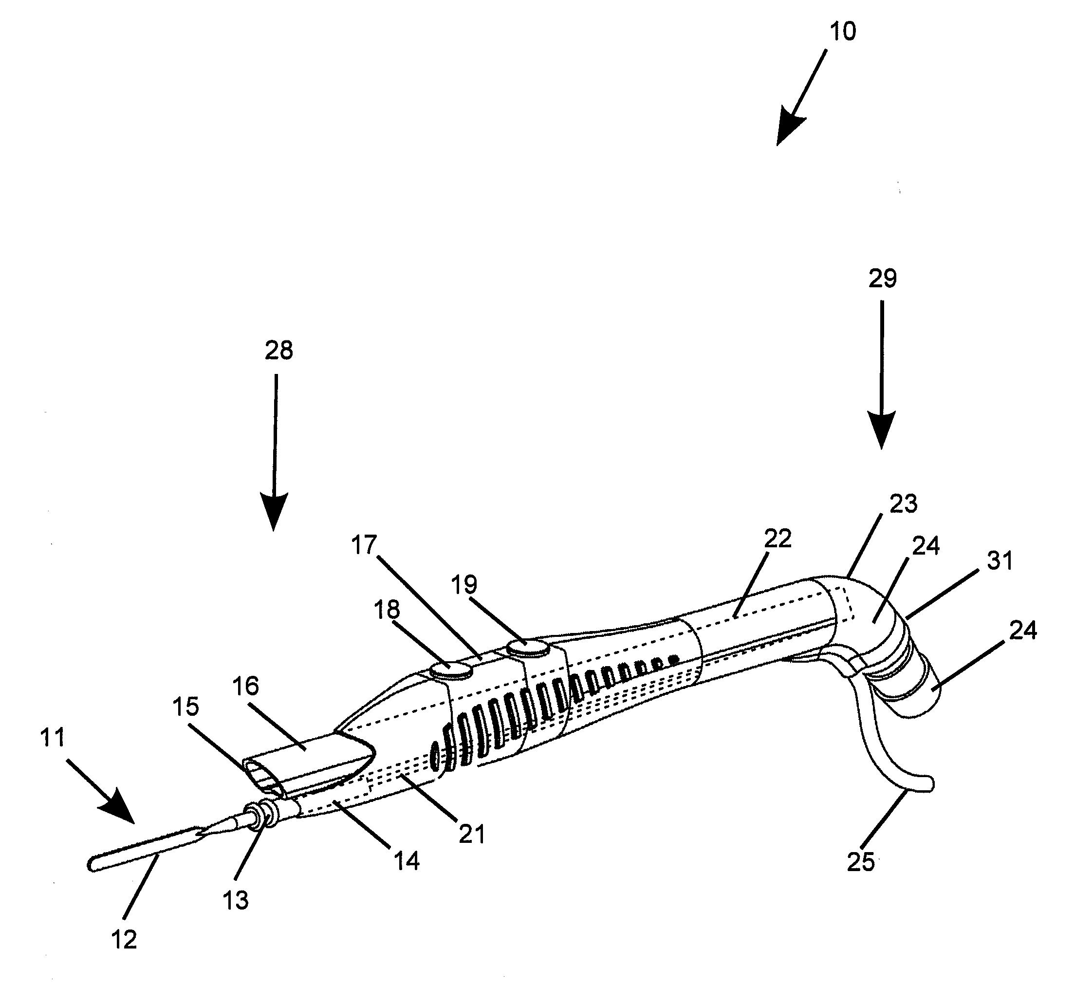
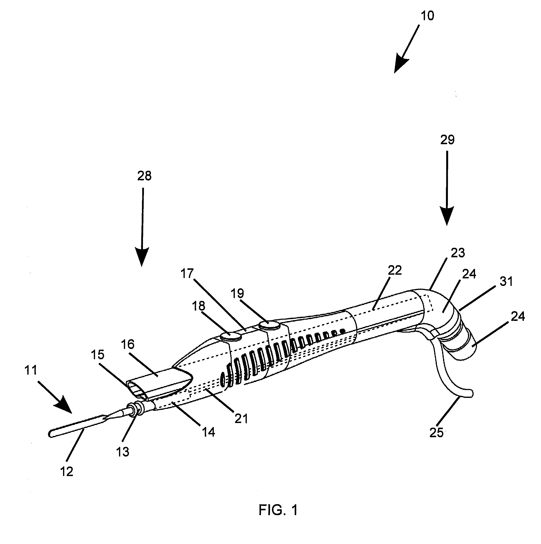
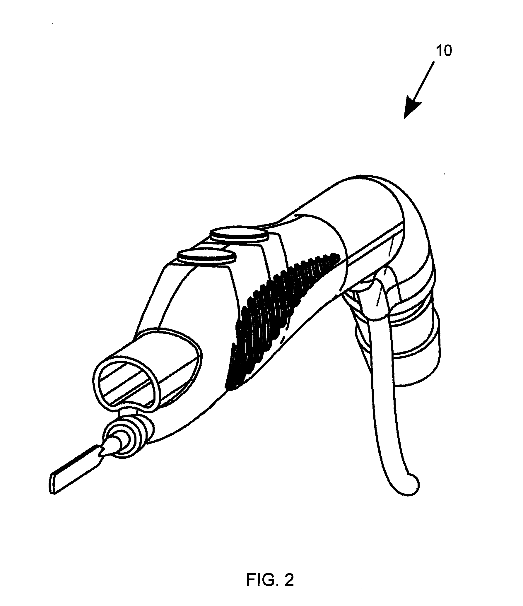
[0014]In another form, an electrosurgical device is provided comprising: an electrode; an elongated hollow body having an internal cavity, a front end, a rear end, an external surface, and an electrical wire arranged within the body, a hollow body is configured to reversibly receive the electrode, in which the hollow body is shaped to have an ergonometric orientation complementary to a user's hand; a first button for controlling a current flow at a first level to the electrode and arranged on the external surface; a vacuum tube engaged by the body and having an inlet generally facing the front end, the vacuum tube arranged adjacent the electrode and the inlet having a substantially vertical cross section when the device is held in the ergonometric orientation. A vacuum outlet port may be arranged near the rear end, and the outlet port, internal cavity, and vacuum inlet are in fluid communication with each other.
[0015]The devic...

Problems solved by technology

This heat vaporizes the intracellular fluid, which increases the pressure inside the cell and eventually causes the cell membrane to burst.
At the same time, the heat created may char the protein and other organic matter within the cell, and may cause thermal necrosis in adjacent cells.
The charring of cells may also release other harmful contaminants, such as carbonized cell fragments and gaseous hydrocarbons.

Method used


Image

  • Electrosurgical device with vacuum port
  • Electrosurgical device with vacuum port
  • Electrosurgical device with vacuum port

Examples


Embodiment Construction

[0023]At the outset, it should be clearly understood that like reference numerals are intended to identify the same structural elements, portions or surfaces consistently throughout the several drawing figures, as such elements, portions or surfaces may be further described or explained by the entire written specification, of which this detailed description is an integral part. Unless otherwise indicated, the drawings are intended to be read (e.g., cross-hatching, arrangement of parts, proportion, degree, etc.) together with the specification, and are to be considered a portion of the entire written description of this invention. As used in the following description, the terms “horizontal”, “vertical”, “left”, “right”, “up” and “down”, as well as adjectival and adverbial derivatives thereof (e.g., “horizontally”, “rightwardly”, “upwardly”, etc.), simply refer to the orientation of the illustrated structure as the particular drawing figure faces the reader. Similarly, the terms “inwa...


PUM


Abstract

An electrosurgical device comprising: an electrode having a first portion whose exterior is electrically uninsulated, a second portion whose exterior is electrically insulated, and a third portion; an elongated hollow body having an internal cavity, a front end, a rear end, an external surface, and an electrical wire arranged within the body. The hollow body is configured to reversibly receive the third portion of the electrode at the front end of the body such that electrical contact is made between the electrode and the electrical wire and the second portion of the electrode is not surrounded by the hollow body. A first button is provided for controlling a current flow at a first level to the electrode and is arranged on the external surface. A vacuum tube is slidably engaged by the body and has an inlet generally facing the front end and adjacent the electrode. A vacuum outlet port is arranged near the rear end of the body, and the outlet port, internal cavity, and vacuum inlet are in fluid communication with each other.

Description

CROSS-REFERENCE TO RELATED APPLICATIONS[0001]The present application claims the benefit of U.S. Provisional Application No. 61 / 301,328, filed Feb. 4, 2010, and U.S. Provisional Application No. 61 / 318,023, filed Mar. 26, 2010, each of which is hereby incorporated by reference.FEDERALLY SPONSORED RESEARCH[0002]Not applicable.TECHNICAL FIELD[0003]The present invention relates generally to smoke evacuation and, more specifically, to an electrosurgical device with smoke evacuation during medical procedures.BACKGROUND[0004]Surgical smoke and aerosol, or plume, is created in connection with surgery. For example, when laser or electrosurgical energy is delivered to a cell, heat is created. This heat vaporizes the intracellular fluid, which increases the pressure inside the cell and eventually causes the cell membrane to burst. In this example, a plume of smoke containing water vapor is released into the atmosphere of the operating room or doctor's office. At the same time, the heat created ...

Claims


Application Information

Patent Timeline
IPC IPC(8): A61B18/18
CPCA61B18/18A61B18/1402A61B2218/008A61B18/14A61B2218/007A61B2018/00178A61B90/30A61B2018/1475
Inventor SHVETSOV, KYRYLOLIZAUCKAS, III, ANTHONY L.PEPE, GREGORY J.PALMERTON, DANIEL R.LYNCH, JOSEPH J.PALMERTON, CHRISTOPHER A.
Owner BUFFALO FILTER
Learn More