Cylinder device

a cylinder and cylinder body technology, applied in the direction of fluid couplings, servomotors, couplings, etc., can solve the problems of deterioration of responsiveness, inability to mount on various vehicles including railroad vehicles, and extended overall length of the cylinder device, so as to reduce manufacturing costs, improve productivity, and prevent deterioration of responsiveness to thrust generation

Active Publication Date: 2011-08-11
KYB CORP
View PDF9 Cites 41 Cited by
  • Summary
  • Abstract
  • Description
  • Claims
  • Application Information

AI Technical Summary

Benefits of technology

[0012]The present invention has been achieved to improve the above-mentioned drawbacks, and one of the objects of the present invention is to improve the mountability on vehicles of a cylinder device. Another object of the present invention is to attain improvement in productivity and reduction in cost in terms of manufacturing and maintenance of the cylinder device. A further object of the present invention is to improve the calmness of the cylinder device, and an additional object of the present invention is to improve the economic performance of the cylinder device.
[0020]This cylinder device, when forcedly extended and contracted by external force, can behave as a damper by stopping the drive of the pump, and can suppress the vibration of a vibration control object by semiactive control typified by skyhook semiactive control, as well as suppressing the vibration of the vibration control object by the active control by the behavior as actuator. Thus, since the cylinder device can be controlled by selecting, of the active control and the semiactive control, the one most suitable to vibration suppression according to the vibration mode, the vibration suppressing effect on the vibration control object is improved.

Problems solved by technology

The resulting extended overall length of the cylinder device leads to a drawback in terms of mountability on various vehicles including railroad vehicle.
Further, although it is necessary to rapidly discharge gas within the working chambers out of the cylinder since entrapment of gas into the working chambers or penetration of gas which was originally blended into oil to the working chambers as bubbles during decompression disables development of on-target thrust due to the compressibility of the gas and causes deterioration of the responsiveness to thrust generation, the conventional cylinder device configured to simply introduce and discharge oil to and from each working chamber during operation has a structure difficult to spontaneously discharge the gas out of the working chambers by the operation of the device.
Therefore, the assembling process of the cylinder device requires consideration for high-level deaeration of the oil to be injected as occasion demands, in addition to assembling in oil or assembling under vacuumed environment and, at any rate, the cylinder device has a drawback on the productivity and requires an increased cost.
Further, the cylinder device is forced to be periodically maintained, since the gas cannot be spontaneously discharged once entrapped into the working chambers as described above, and the only way to recover the performance is a maintenance involving disassembling or the like.
Therefore, the cost burden can be increased also in terms of maintenance, in addition to the necessity of labor hour.

Method used


Image

  • Cylinder device
  • Cylinder device
  • Cylinder device

Examples


Embodiment Construction

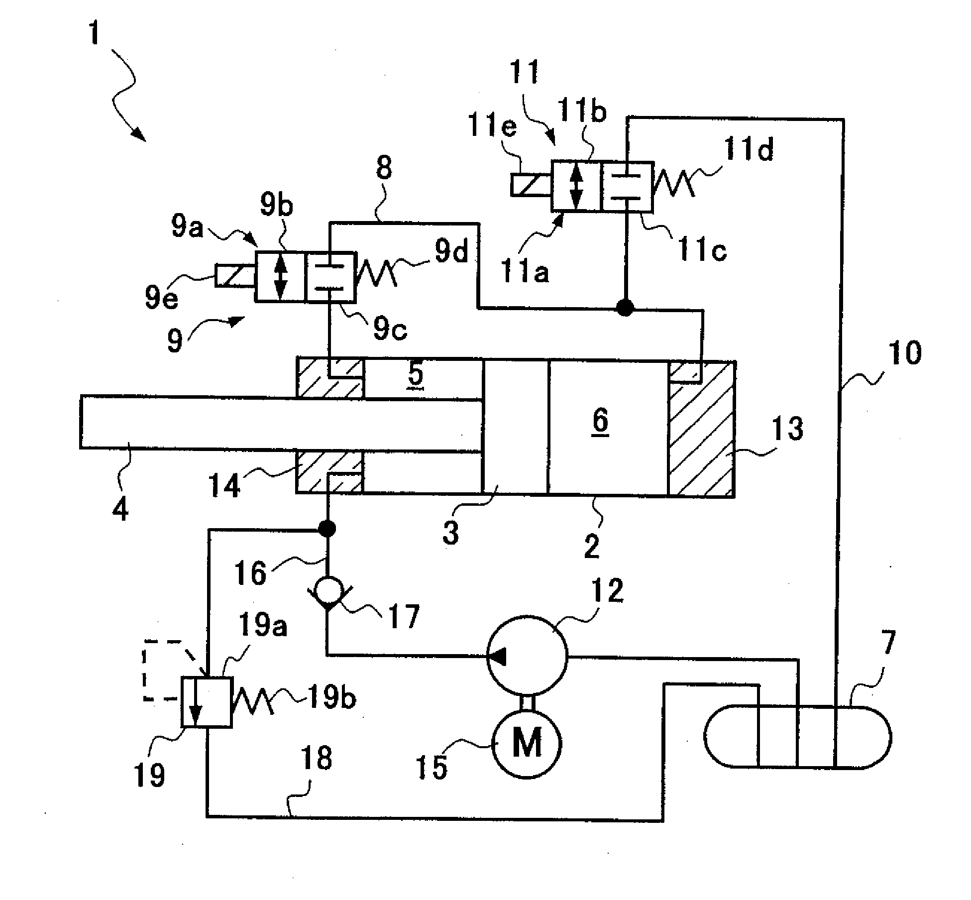
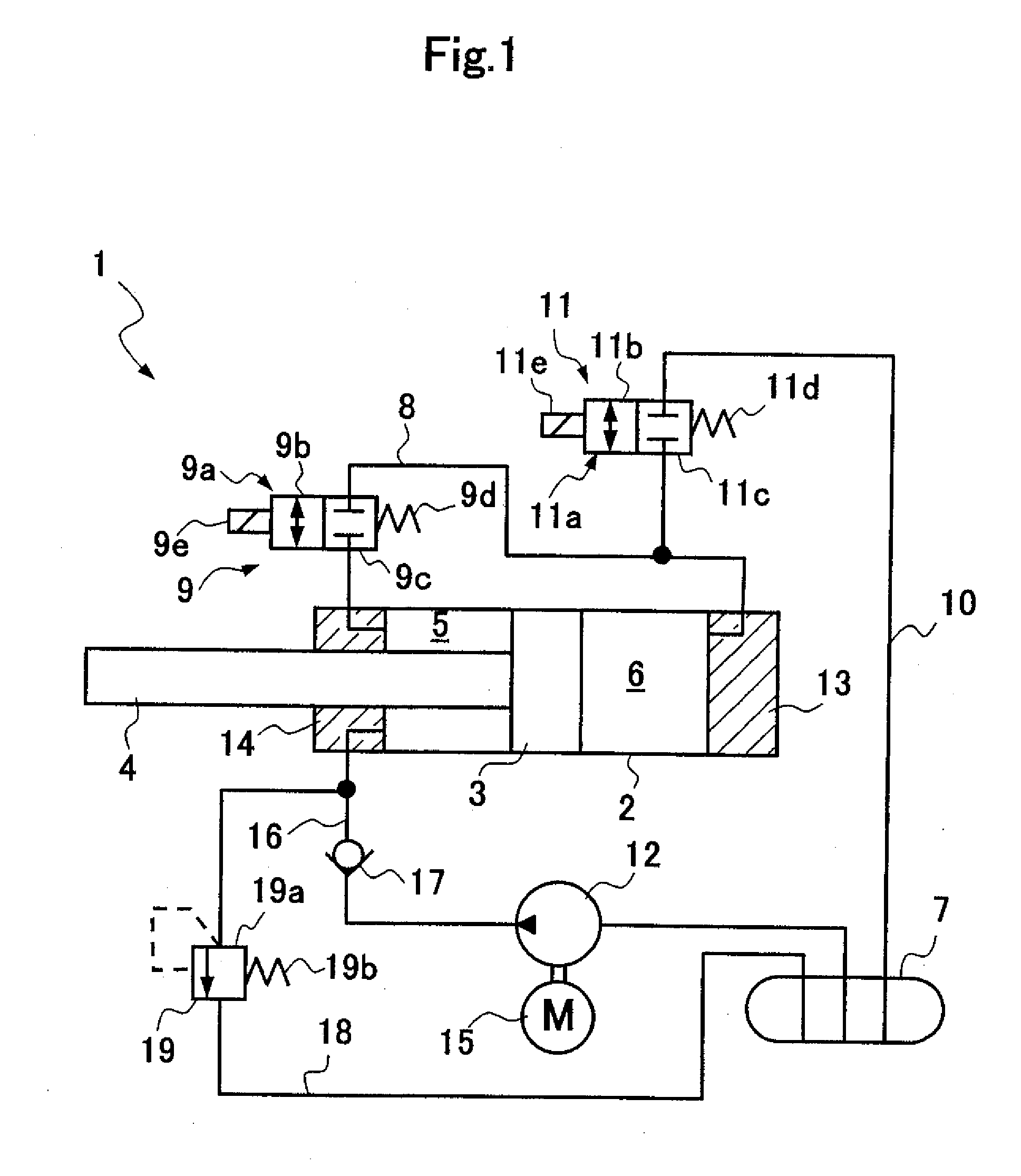
[0027]A cylinder device 1 according to one embodiment is basically constituted as a single-rod cylinder device, as shown in FIG. 1, which includes a cylinder 2; a piston 3 inserted slidably into the cylinder 2; a rod 4 inserted into the cylinder 2 and connected to the piston 3; a rod-side chamber 5 and a piston-side chamber 6 partitioned by the piston 3 within the cylinder 2; a tank 7; a first on-off valve 9 provided in the middle of a first passage 8 allowing the rod-side chamber 5 to communicate with the piston-side chamber 6; a second on-off valve 11 provided in the middle of a second passage 10 allowing the piston-side chamber 6 to communicate with the tank 7; and a pump 12 for supplying liquid to the rod-side chamber 5. The rod-side chamber 5 and the piston-side chamber 6 are filled with liquid such as hydraulic oil, and the tank 7 is filled with gas in addition to the liquid. The inside of the tank 7 does not have to be in a pressurized state particularly by filling the gas wi...


PUM


Abstract

A cylinder device (1) according to the present invention includes: a cylinder (2); a piston (3) slidably inserted into the cylinder (2); a rod (4) inserted into the cylinder (2) and connected to the piston (3); a rod-side chamber (5) and a piston-side chamber (6) partitioned by the piston (3) within the cylinder (2); a first on-off valve (9) provided in the middle of a first passage (8) allowing the rod-side chamber (5) to communicate with the piston-side chamber (6); a second on-off valve (11) provided in the middle of a second passage (10) allowing the piston-side chamber (6) to communicate with the tank (7); and a pump (12) for supplying liquid to the rod-side chamber (5).

Description

FIELD OF THE INVENTION[0001]The present invention relates to an improved cylinder device.DESCRIPTION OF THE RELATED ART[0002]This type of cylinder devices is conventionally known to be applied to, for example, a railroad vehicle to suppress vibrations in lateral direction relative to an advancing direction of a vehicle body by being interposed between the vehicle body and a truck.[0003]Such a cylinder device is disclosed, for example, in Japanese Patent Application Laid-Open No. 2005-7944 or 2006-137294, and is constituted as a double-rod type, including, as shown in FIG. 6, a cylinder 100, a piston 101 slidably inserted into the cylinder 100, a rod 102 inserted into the cylinder 100 with a middle portion thereof being connected to the piston 101, and a hydraulic circuit 105 for selectively supplying pressure oil to one of two working chambers 103 and 104 partitioned by the piston 101 within the cylinder 100.[0004]More specifically, the hydraulic circuit 105 includes a two-way disch...

Claims


Application Information

Patent Timeline
Patent Type & Authority Applications(United States)
IPC IPC(8): F15B1/26F15B15/14
CPCB61F5/245F15B21/14F15B15/149F15B1/26F15B11/028F15B15/1428F15B2211/30505F15B2211/3058F15B2211/31529F15B2211/50518F15B2211/5159F15B2211/7053F15B2211/76F15B2211/8613Y10T137/87507B61F5/24F16F15/027F15B11/024F15B13/021
Inventor OGAWA, TAKAYUKI
Owner KYB CORP
Why Eureka
Try Eureka