Apparatus with abnormality determination function and method for determining abnormality

a technology of abnormality and determination function, applied in mechanical apparatus, machines/engines, instruments, etc., can solve the problems of difficult use, very complex apparatus constitution, and method as inspection method, and achieve the effect of easy self-diagnosis

Inactive Publication Date: 2011-08-11
NGK INSULATORS LTD +1
View PDF6 Cites 17 Cited by
  • Summary
  • Abstract
  • Description
  • Claims
  • Application Information

AI Technical Summary

Benefits of technology

[0017]In an apparatus with an abnormality determination function of the present invention, in an apparatus provided with an electrode portion having at least three electrodes, self-diagnosis of an abnormality of the electrode portion can be performed easily. In addition, in a method for determining an abnormality of the present invention, an abnormality of the aforementioned electrode portion having at least three electrode can easily be determined.
[0018]In the present invention, in the case that another conductor (e.g., another electrode) is disposed near a conductor (e.g., one electrode) where an alternating-current voltage is applied, the magnitude of electric current flowing between electrically independent electrodes via a dielectric body is measured by the use of a phenomenon (hereinbelow sometimes referred to as “electrostatic coupling”) of induction of electric charge due to generation of floating capacitance between the conductors, thereby determining (inspecting) an abnormality of each of the electrodes. Further, a apparatus with an abnormality determination function of the present invention can not only determine (inspect) presence / absence of an abnormality, but also restrict or identify the position of the abnormality when an abnormality is determined.
[0019]That is, in the present invention, at least two different combinations of two electrodes are selected from the electrode portion having at least three electrodes, the current value of each of the at least two combinations is measured, and the measurement values are compared with each other to be able to determine an abnormality of the apparatus and further restrict or identify the portion of the abnormality.
[0020]This enables to easily conduct self-diagnosis of an abnormality of the aforementioned electrode portion. For example, even with a very small apparatus, an abnormality can be determined well. For example, in a particulate matter detection apparatus having specific constitution for detecting particulate matter in exhaust gas, whether the detection of particulate mater is performed normally or not is judged, and a damage or defect of the apparatus can be inspected well.

Problems solved by technology

However, in such a conventional inspection method, since the pin probes have to be changed according to the damage of the conductive pattern due to the contact of the pin probes or according to the pitch of the conductive pattern, the method is very troublesome as an inspection method.
However, the aforementioned conductive pattern inspection apparatus described in JP-A-2005-24518 has a problem of very complex constitution of the apparatus because the current value is measured with moving the sensor electrode sequentially with respect to the conductive pattern (e.g., electrode).
However, since such a particulate matter detection apparatus is sometimes very small and therefore has a problem of having much difficulty in employing the constitution described in JP-A-2005-24518 from the viewpoint of the constitution of the apparatus.

Method used


Image

  • Apparatus with abnormality determination function and method for determining abnormality
  • Apparatus with abnormality determination function and method for determining abnormality
  • Apparatus with abnormality determination function and method for determining abnormality

Examples


example 1

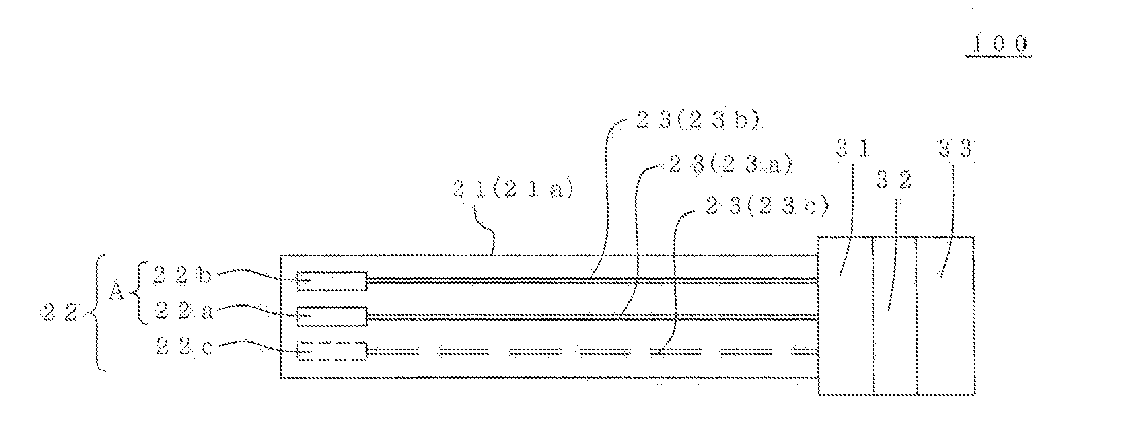
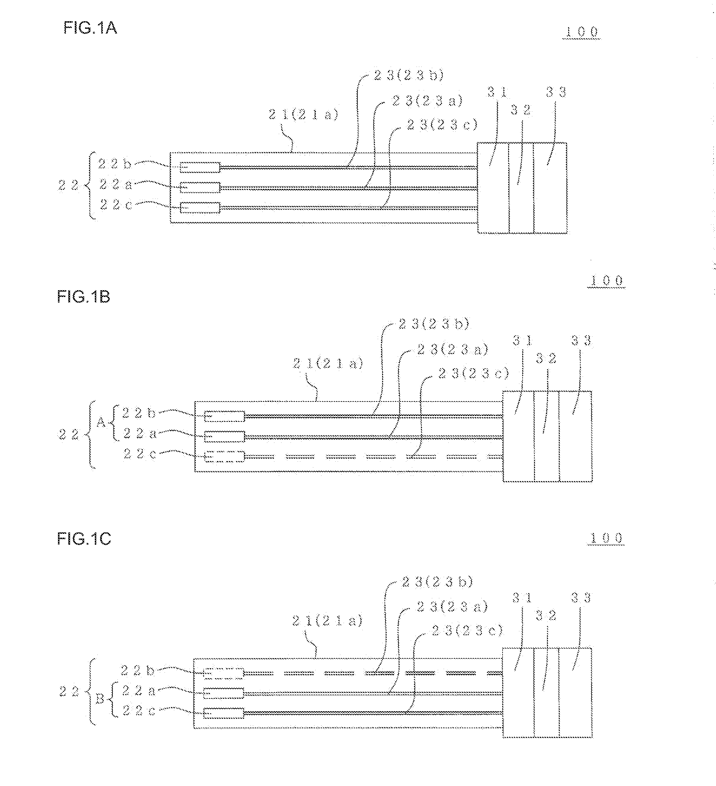
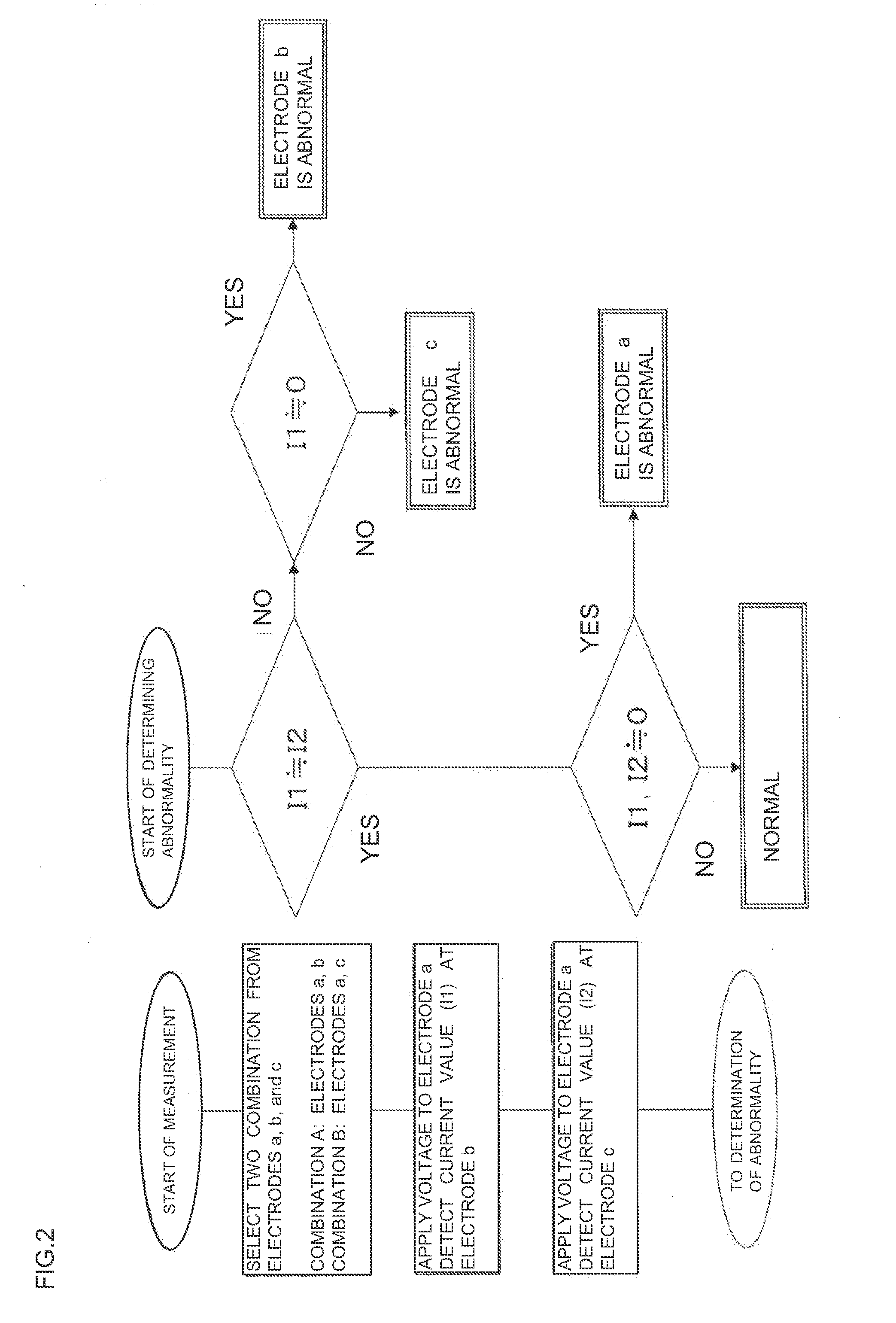
[0175]The abnormality determination by the abnormality determination means was performed with the aforementioned detection apparatus (1). In the first place, two combinations (one combination was defined as “combination A”, while the other combination was defined as “combination B”) were selected from the measurement electrodes and the dust-collecting electrodes by the abnormality determination means. Specifically, the combination of the high voltage dust-collecting electrode and the one measurement electrode was defined as the combination A, and the combination of the high voltage dust-collecting electrode and the other measurement electrode was defined as the combination B.

[0176]Next, in the combination A, an alternating-current voltage of 1 kHz and 100V was applied to the high voltage dust-collecting electrode to measure a current value flowing in the one measurement electrode selected for the combination A. The current value was 57 nA. Next, the same measurement was performed fo...

example 2

[0178]The aforementioned detection apparatus (2) was inspected in the same manner as in Example 1. Since the current value of the combination A was 0 nA, disconnection was suspected in one of the high voltage dust-collecting electrode and the measurement electrode. However, since the current value of the combination B was 60 nA (i.e., “not0”) and close to the normal value to be fundamentally expected, the high voltage dust-collecting electrode was normal, and, from the current value of the combination A, it could be judged as disconnection of the measurement electrode.

example 3

[0179]The aforementioned inspection apparatus (3) was measured in the same conditions as Example 1 with defining the combination of the dust-collecting electrode and the one measurement electrode as the combination A and the combination of the dust-collecting electrode and the other measurement electrode as the combination B. As a result, the current value of the combination A was 0 nA, and the current value of the combination B was 0 nA. Therefore, it was judged that at least the dust-collecting electrode included in both the combinations had disconnection.

[0180]Next, in order to judge abnormality of the one measurement electrode and the other measurement electrode other than the dust-collecting electrode, the combination of the high voltage dust-collecting electrode and the one measurement electrode was determined as the combination A, and the combination of the high voltage dust-collecting electrode and the other measurement electrode was determined as the combination B to perfor...


PUM

PropertyMeasurementUnit
alternating-current voltageaaaaaaaaaa
currentaaaaaaaaaa
current valueaaaaaaaaaa

Abstract

The apparatus 100 is provided with an abnormality determination means 32 for determining abnormality of the apparatus 100 where two different combinations of two electrodes are selected from the three electrodes 22a, 22b, and 22c, an alternating-current voltage is applied to an electrode in one combination by the voltage-applying portion 31 to measure a value of a current flowing to the other electrode via the dielectric body 21a by electrostatic coupling, an alternating-current voltage is applied to an electrode in another combination out of the at least two different combinations by the voltage-applying portion 31 to measure a value of a current flowing to the other electrode via the dielectric body 21a by electrostatic coupling, and an abnormality of the apparatus 100 is determined from the current values measured.

Description

BACKGROUND OF THE INVENTION AND RELATED ART STATEMENT[0001]The present invention relates to an apparatus with an abnormality determination function and a method for determining an abnormality. More specifically, the present invention relates to an apparatus with an abnormality determination function, the apparatus being capable of easily performing a self-diagnosis of an abnormality of the electrode portion in an apparatus provided with an electrode portion having at least three electrodes and to a method for determining an abnormality to easily determine an abnormality of the electrode portion.[0002]As a method for inspecting (determining) an abnormality of an apparatus provided with a substrate at least a part of which is constituted of a dielectric body and an electrode disposed on the surface or in the internal portion of the dielectric body constituting the substrate, there has been used, for example, a method where pin probes are bought into contact with both the ends of a con...

Claims


Application Information

Patent Timeline
Patent Type & Authority Applications(United States)
IPC IPC(8): G01R35/00G01N27/02
CPCF01N2560/12G01N27/4163G01N15/0656G01N35/00623F01N2560/05G01N2015/0046G01N15/0606F01N2560/026
Inventor YOKOI, SHOJISAKURAI, TAKAYUKIOKAYAMA, TATSUYAMIKI, MASANOBUIWAMA, KEIZOHATTORI, MAKOTOOZAWA, HIDETAKA
Owner NGK INSULATORS LTD
Why Eureka
Try Eureka