Stress sensing device, tactile sensor, and grasping apparatus

a sensing device and tactile sensor technology, applied in the direction of force/torque/work measurement apparatus, manufacturing tools, instruments, etc., can solve the problem of inability to accurately sense the pressing force applied at a location, the large sensor size is unsuitable for small-scale tactile sensor production, and the pressing force acting on a location where a structure for sensing shear force is disposed cannot be accurately sensed

Active Publication Date: 2011-08-11
SEIKO EPSON CORP
View PDF14 Cites 44 Cited by
  • Summary
  • Abstract
  • Description
  • Claims
  • Application Information

AI Technical Summary

Benefits of technology

[0009]With the foregoing in view, it is an object of the present invention to provide a stress sensing device, a tactile sensor, and a grasping apparatus adaptable to compact design, and capable of accurately sensing shear force and pressing force.
[0034]According to this invention, by providing a tactile sensor as taught above, both shear force and pressing force may be sensed accurately when an object is grasped; and based on the sensed shear force and pressing force, it is possible to appropriately determine whether the object is slipping from the grasp arms, or grasped securely. Specifically, during an operation for grasping an object, shear force arises in response to kinetic friction under conditions in which the object cannot be grasped adequately, and as grasping force intensifies, this shear force increases as well. Meanwhile, a condition of intensifying grasping force until shear force in response to static friction is sensed represents a condition in which the object is grasped completely, and even if grasping force intensifies further, static friction is constant and therefore shear force does not change either. Consequently, by progressively increasing the force with which an object is grasped and by sensing the point in time that shear force no longer changes, it is possible for the object to be grasped with the minimum force necessary, without breaking the object.

Problems solved by technology

However, where the structures for sensing shear force and the structures for sensing pressing force are formed in separate regions in this way, a resultant problem is larger sensor size unsuited to production of small-scale tactile sensors.
Therefore, a resultant problem is that pressing force acting on a location where a structure for sensing shear force is disposed cannot be sensed accurately.
In this regard, where separate elements are provided in order to detect shear force and pressing force, it is not possible to accurately sense pressing force applied at a location where a shear force sensor is disposed or shear force applied at a location where a pressing force sensor is disposed, for example.
Moreover, where elements for sensing shear force and elements for sensing pressing force are respectively formed as separate elements, it is necessary to ensure space equivalent to two elements in order to configure a sensor for sensing shear force and pressing force, resulting in large sensor size.

Method used


Image

  • Stress sensing device, tactile sensor, and grasping apparatus
  • Stress sensing device, tactile sensor, and grasping apparatus
  • Stress sensing device, tactile sensor, and grasping apparatus

Examples


first embodiment

[0051]A first embodiment of a stress sensing device according to the present invention is described below based on the drawings.

1. Configuration of Stress Sensing Device

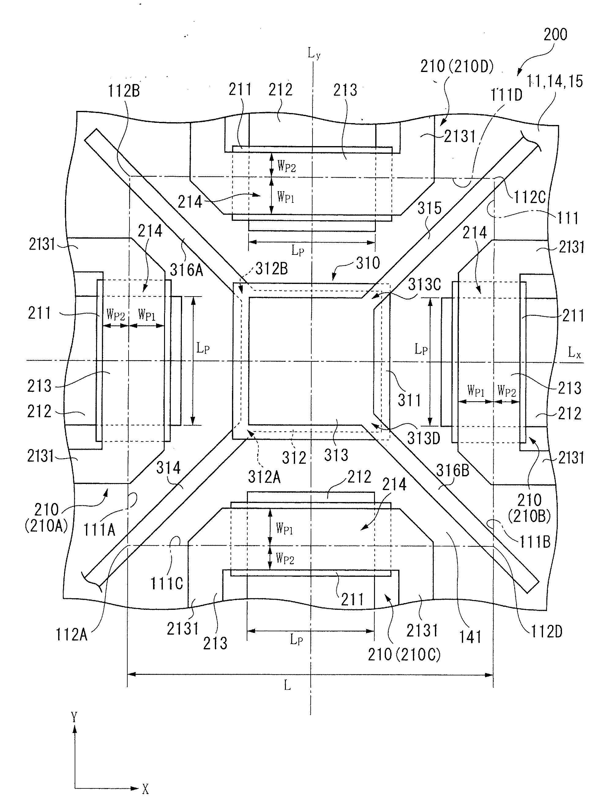
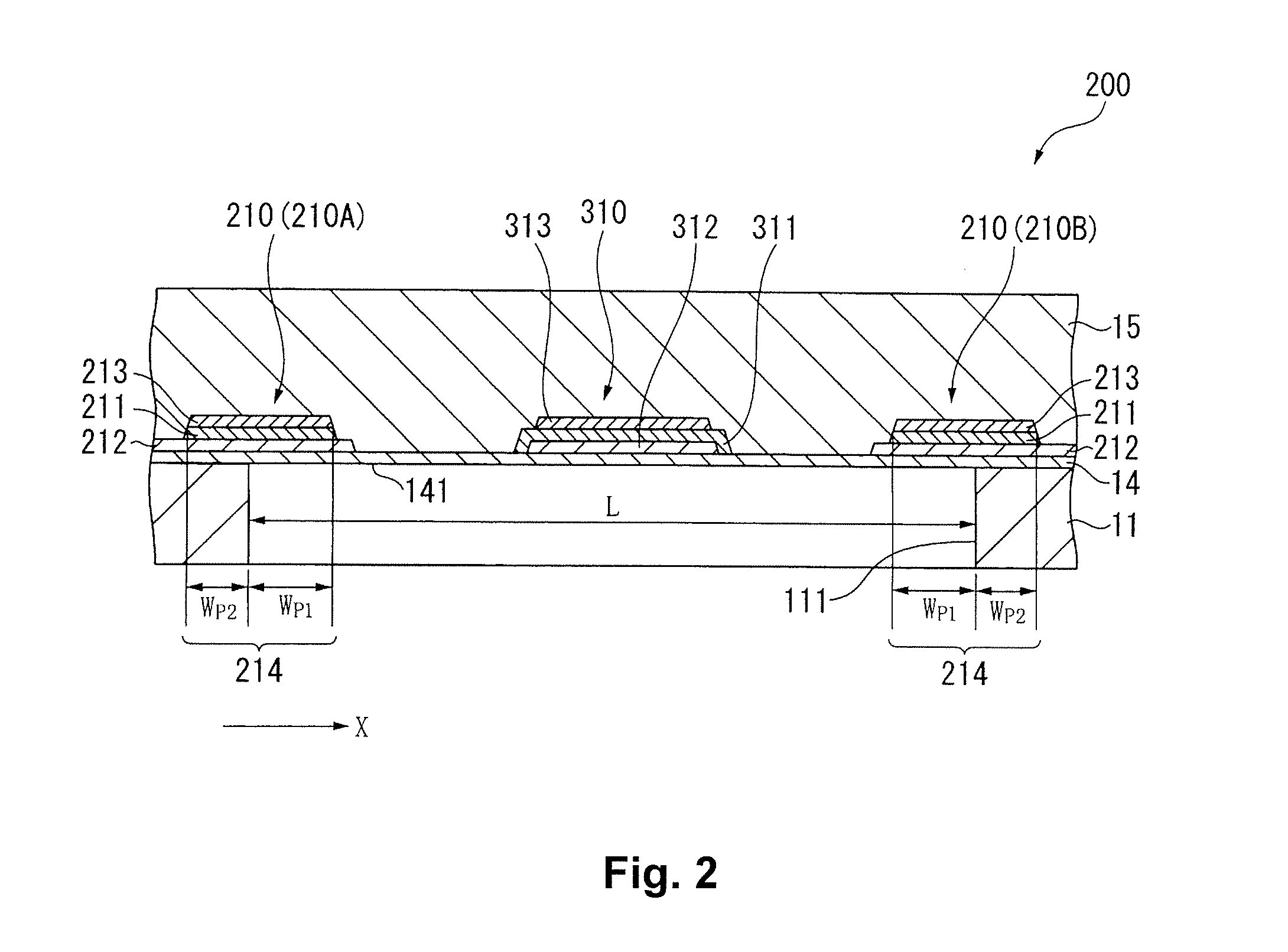
[0052]FIG. 1 is a plan view depicting a simplified configuration of a stress sensing device 200 according to the first embodiment; and FIG. 2 is a sectional view of the stress sensing device 200.

[0053]As shown in FIG. 1, the stress sensor element 200 is composed of a sensor substrate 11 provided as the support body, and laminated thereon are a support film 14, shear force sensing piezoelectric bodies 210 provided as first piezoelectric parts according to the present invention, a pressing force sensing piezoelectric body 310 provided as a second piezoelectric part according to the present invention, and an elastic layer 15 provided as the elastic layer. This stress sensor element 200 is an element for sensing pressing force and shear force applied during contact of an object against the elastic layer 15.

1-1. Configura...

second embodiment

[0116]Next, as an application example of the stress sensing device 200 described above, a tactile sensor furnished with the stress sensing device 200 is described based on the drawings.

[0117]FIG. 8 is a fragmentary enlarged plan view of the tactile sensor of the second embodiment.

[0118]FIG. 9 is a fragmentary sectional view of the tactile sensor.

[0119]As shown in FIG. 8, the tactile sensor 10 is furnished with a plurality of the stress sensing devices 200 according to the first embodiment.

[0120]These stress sensing devices 200 are disposed in a matrix arrangement on the sensor substrate 11 that makes up the support body of the present invention. In these stress sensing devices 200, the sensor substrate 11, the support film 14, and the elastic layer 15 are constituted by common members. Specifically, a plurality of openings 111 are formed in a matrix arrangement on a single sensor substrate 11, and a continuous support film 14 is formed over the entire face of one side of this sensor...

third embodiment

[0130]Next, as an application example of a device employing the tactile sensor 10 described above, a grasping apparatus furnished with the tactile sensor 10 is described based on the drawings.

[0131]FIG. 11 is a device block diagram depicting a simplified configuration of a grasping apparatus according to a third embodiment of the present invention.

[0132]In FIG. 11, the grasping apparatus 1 is a device that includes at least one pair of grasping arms 2, and is adapted to grasp an object Z with the grasping arms 2. This grasping apparatus 1 is intended for use in a manufacturing facility for manufacturing products, for example, and the device is adapted to grasp and pick up objects conveyed by a belt conveyor or the like. This grasping apparatus 1 is composed of the grasping arms 2, an arm driving portion 3 for driving the grasping arms 2, and a control unit 4 for drive control of the arm driving portion 3.

[0133]The pair of grasping arms 2 are provided at their respective distal ends ...


PUM

PropertyMeasurementUnit
thicknessaaaaaaaaaa
thicknessaaaaaaaaaa
thicknessaaaaaaaaaa

Abstract

A stress sensing device senses a shear force and a pressing force. The stress sensing device includes a support body, a support film, first and second piezoelectric parts and an elastic layer. The support body has an opening defined by a pair of straight parts perpendicular to a sensing direction of the shear force and parallel to each other. The support film having flexibility closes off the opening. The first piezoelectric part is disposed over the support film and straddling an inside portion and an outside portion of the opening along at least one of the straight parts of the opening as seen in plan view. The second piezoelectric part is disposed to the inside portion of the opening and set apart from the first piezoelectric part as seen in the plan view. The elastic layer covers the first piezoelectric part, the second piezoelectric part, and the support film.

Description

CROSS-REFERENCE TO RELATED APPLICATIONS[0001]This application claims priority to Japanese Patent Application No. 2010-027325 filed on Feb. 10, 2010. The entire disclosure of Japanese Patent Application No. 2010-027325 is hereby incorporated herein by reference.BACKGROUND[0002]1. Technical Field[0003]The present invention relates to a stress sensing device adapted to sense both shear force acting in a shear direction and pressing force acting in a direction perpendicular to a shear direction; to a tactile sensor furnished with this stress sensing device; and to a grasping apparatus furnished with this tactile sensor.[0004]2. Related Art[0005]Grasping apparatus designed to grasp and pick up objects of unknown weight or coefficient of friction by a robot arm, a robot hand, a robot manipulator or the like are known in the art. In a grasping apparatus of this kind, in order to grasp an object without breaking it and without letting the object slip and drop, it is necessary to sense force...

Claims


Application Information

Patent Timeline
Patent Type & Authority Applications(United States)
IPC IPC(8): G01L1/16B25J15/02B25J13/08
CPCB25J13/083G01L5/228G01L5/167
Inventor NISHIWAKI, TSUTOMU
Owner SEIKO EPSON CORP
Why Eureka
Try Eureka