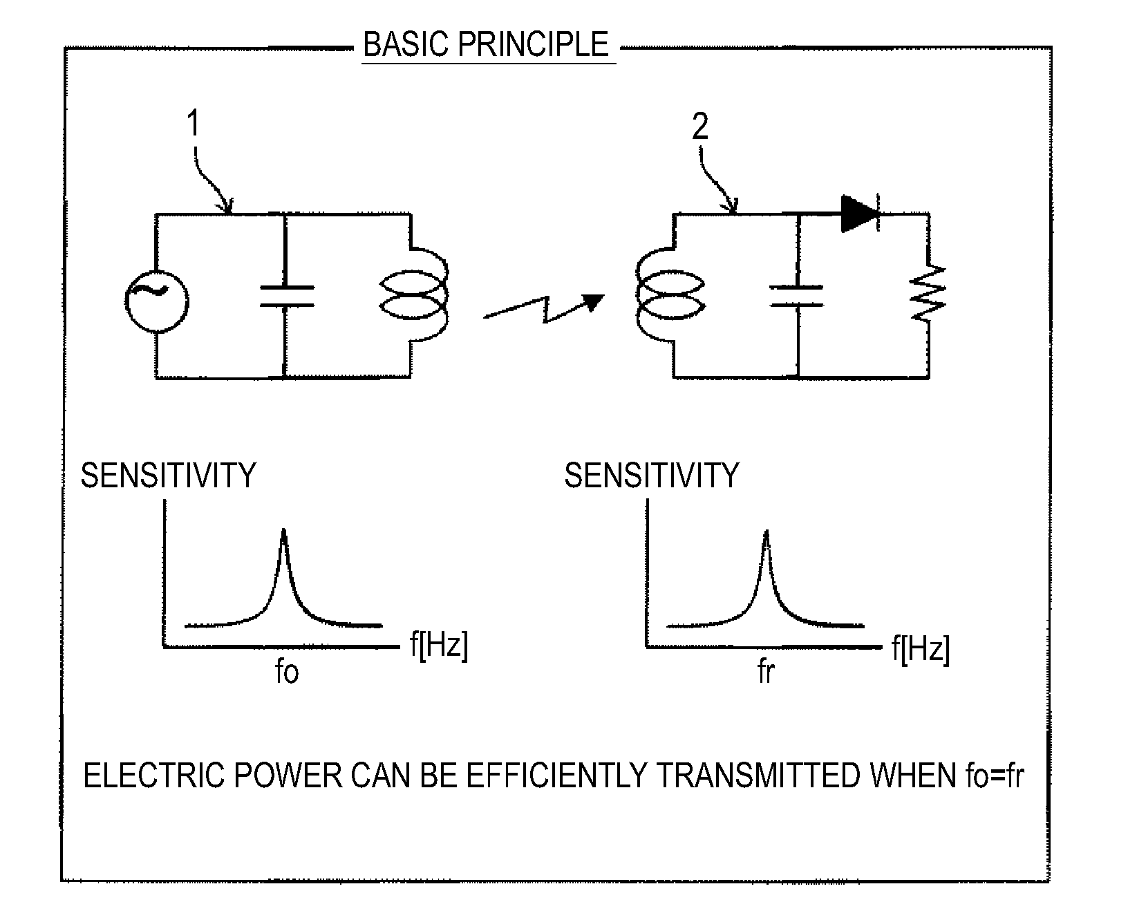
Wireless power transmission apparatus
a power transmission apparatus and wireless technology, applied in the direction of wireless communication, inductance, secret communication, etc., can solve the problems of affecting the peripheral apparatus, prevent the influence of other apparatuses, prevent unnecessary electric power, and prevent the effect of deterioration in power transmission efficiency
- Summary
- Abstract
- Description
- Claims
- Application Information
AI Technical Summary
Benefits of technology
Problems solved by technology
Method used
Image
Examples
first embodiment
1. First Embodiment
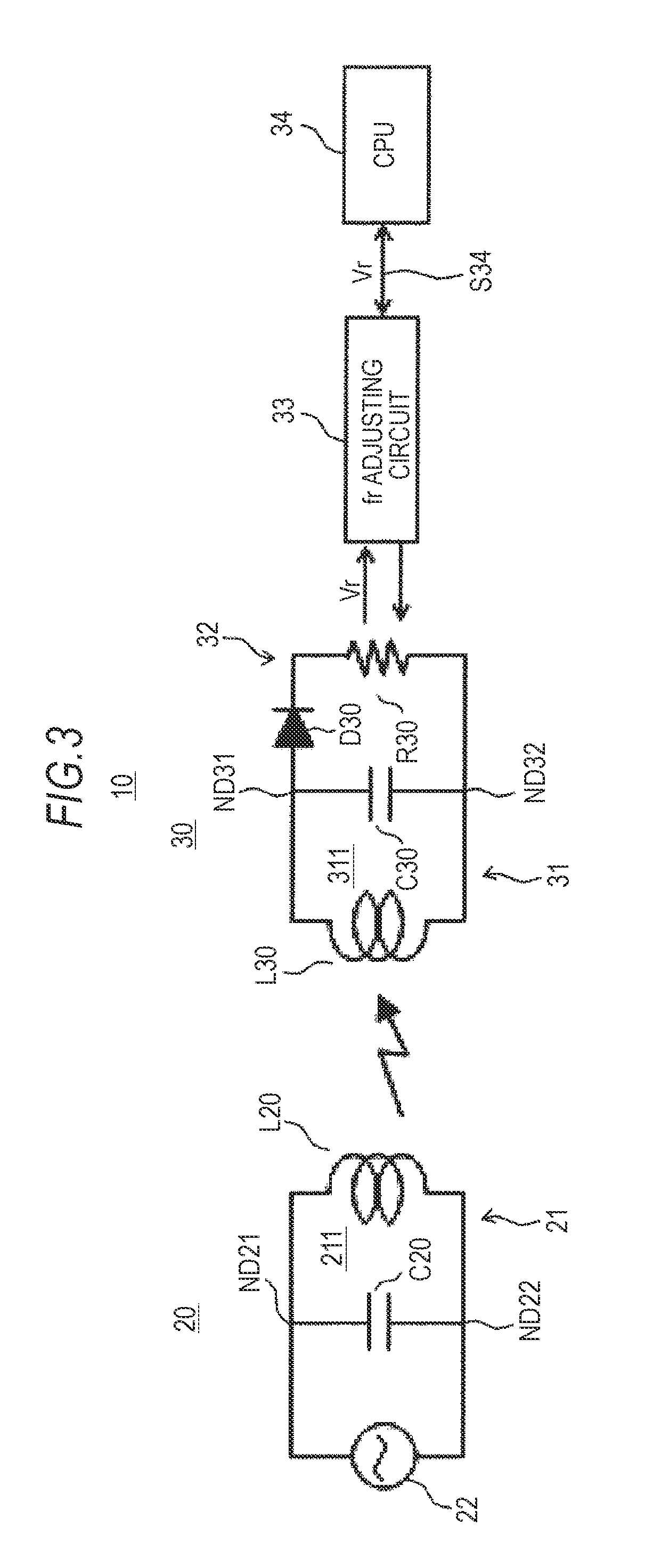
[0086]FIG. 3 is a diagram of a basic configuration of a wireless power transmission apparatus according to a first embodiment of the present invention.
[0087]FIG. 4 is a diagram for explaining an automatic adjustment function for equalizing a reception antenna resonant frequency in a receiver with a transmission antenna resonant frequency according to the first embodiment.
[0088]A wireless power transmission apparatus 10 includes a transmitter 20 and a receiver 30.
[0089]The wireless power transmission apparatus 10 has, on the receiver 30 side, a function of automatically changing a reception antenna resonant frequency fr to equalize a transmission antenna resonant frequency fo of the transmitter 20 and the reception antenna resonant frequency fr of the receiver 30.
[0090]The transmitter 20 includes a transmission antenna unit and a high-frequency generating circuit for power transmission 22.
[0091]The transmission antenna unit 21 equivalently includes an inductor (coi...
second embodiment
2. Second Embodiment
[0135]FIG. 8 is a diagram of a basic configuration of a wireless power transmission apparatus according to a second embodiment of the present invention.
[0136]A wireless power transmission apparatus 10A according to the second embodiment is different from the wireless power transmission apparatus 10 according to the first embodiment as explained below.
[0137]In the wireless power transmission apparatus 10A, a transmitter 20A changes the transmission antenna resonant frequency fo and a receiver 30A causes the reception antenna resonant frequency fr to follow the changed transmission antenna resonant frequency fo.
[0138]FIG. 9 is a schematic diagram for explaining processing for causing the reception antenna resonant frequency to follow a change in the transmission antenna resonant frequency of the wireless power transmission apparatus according to the second embodiment.
[0139]In an example shown in FIG. 9, three frequencies f1, f2, and f3 are switched in order.
[0140]A...
third embodiment
3. Third Embodiment
[0192]FIG. 15 is a diagram of a basic configuration of a wireless power transmission apparatus according to a third embodiment of the present invention.
[0193]FIG. 16 is a diagram of an example of a reception voltage level of a receiver in the wireless power transmission apparatus according to the third embodiment.
[0194]In a wireless power transmission apparatus 10B according to the third embodiment, sequences for changing a resonant frequency according to which a transmitter 20B and a receiver 30B change the resonant frequency are the same.
[0195]The wireless power transmission apparatus 10B is configured such that, the receiver 30B recognizes an fo changing sequence of the transmitter 20B and the transmitter 20B and the receiver 30B change the transmission antenna resonant frequency fo in synchronization with each other.
[0196]By adopting such a configuration, it is possible to reduce a drop of the reception voltage Vr at frequency switching time as shown in FIG. 1...
PUM
 Abstract
Description
Claims
Application Information
 - R&D
- Intellectual Property
- Life Sciences
- Materials
- Tech Scout
- Unparalleled Data Quality
- Higher Quality Content
- 60% Fewer Hallucinations
Browse by: Latest US Patents, China's latest patents, Technical Efficacy Thesaurus, Application Domain, Technology Topic, Popular Technical Reports.
© 2025 PatSnap. All rights reserved.Legal|Privacy policy|Modern Slavery Act Transparency Statement|Sitemap|About US| Contact US: help@patsnap.com


