Logarithmic mean-square power detector

a power detector and logarithmic mean-square technology, applied in the direction of moving-iron instruments, instruments, gain control, etc., can solve problems such as inacceptable errors

Active Publication Date: 2011-08-11
HITTITE MICROWAVE LLC
View PDF27 Cites 6 Cited by
  • Summary
  • Abstract
  • Description
  • Claims
  • Application Information

AI Technical Summary

Benefits of technology

[0003]A mean square power detector in accordance with one or more embodiments includes a gain or attenuation circuit comprising a plurality of gain or attenuation elements arranged for generating a plurality of amplified or attenuated versions of a radio frequency (RF) input signal. The mean square power detector also includes a plurality of mean square detectors coupled to the gain or attenuation circuit. Each of the mean square detectors receives a different one of the pluralit

Problems solved by technology

Intolerable errors can result if conventional power detectors

Method used


Image

  • Logarithmic mean-square power detector
  • Logarithmic mean-square power detector
  • Logarithmic mean-square power detector

Examples


Embodiment Construction

Logarithmic Mean-Square Power Detector

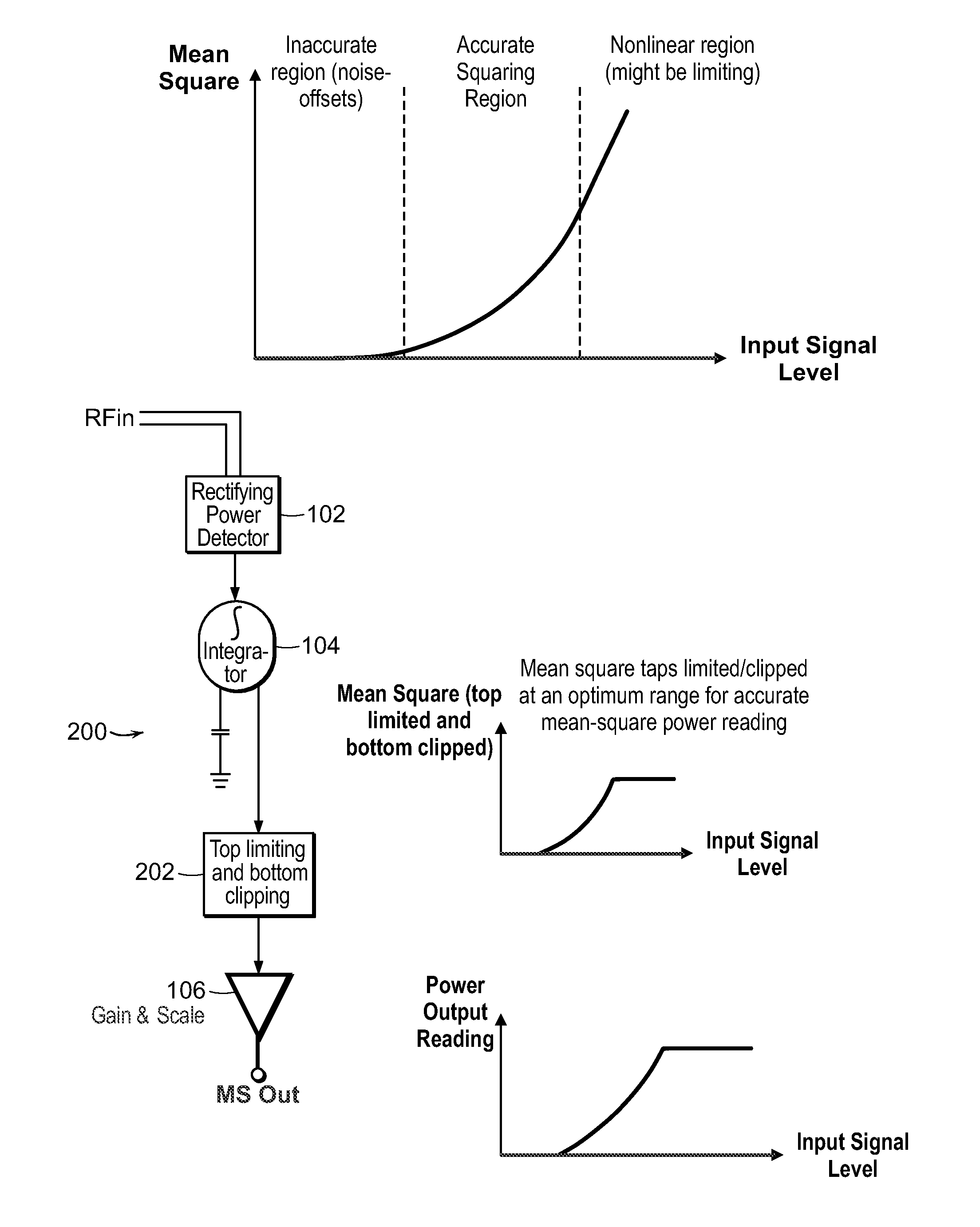
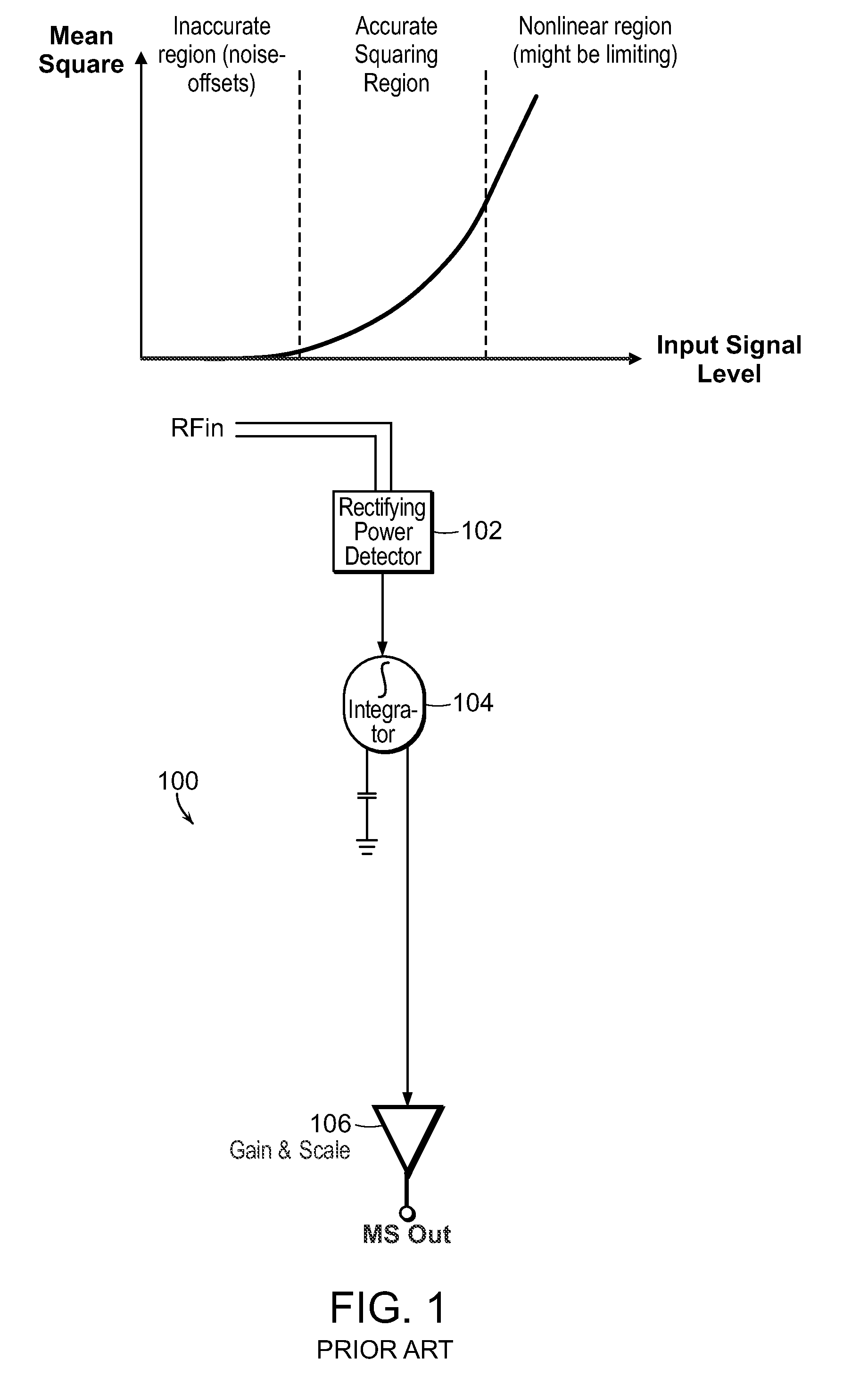
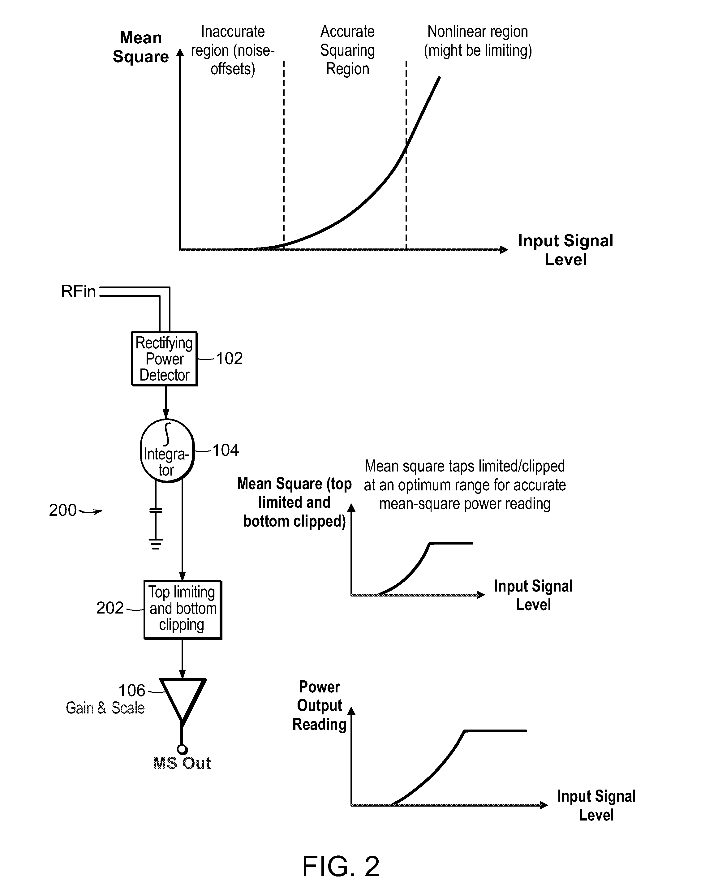
[0029]One or more embodiments of the invention are directed to a detector circuit that accepts a modulated or un-modulated radio frequency (RF) input signal and provides an output that varies as a quasi-linear function of the logarithm of the mean of the square of the RF input signal voltage. The circuit provides an output that varies generally linearly in dB with mean square (MS) voltage of the RF input signal. As the logarithm of the square root of a number is simply half the logarithm of that number, this logarithmic output function of the MS voltage can also serve as a measure of the root mean square (RMS) of the RF input signal voltage just by assuming a different output scaling factor. The circuit provides a wide dynamic range of power detection for input signals with improved output linearity. In some embodiments, the integration bandwidth for the MS calculation is adjustable by the user with external control signals.

[0030]FIG. 1 schemati...


PUM


Abstract

A mean square power detector in accordance with one or more embodiments includes a gain or attenuation circuit comprising a plurality of gain or attenuation elements arranged for generating a plurality of amplified or attenuated versions of a radio frequency (RF) input signal. The mean square power detector also includes a plurality of mean square detectors coupled to the gain or attenuation circuit. Each of the mean square detectors receives a different one of the plurality of amplified or attenuated versions of the RF input signal. Each of the plurality of mean square detectors generates an output signal representative of the mean square power of the RF input signal for a different input signal level range. A summing element is coupled to the plurality of mean square detectors for combining the output signals of the plurality of mean square detectors to generate a signal representative of the mean square or root mean square of the RF input signal.

Description

CROSS REFERENCE TO RELATED APPLICATIONS[0001]This application claims priority from (1) U.S. Provisional Patent Application Ser. No. 61 / 263,668, filed on Nov. 23, 2009, entitled Logarithmic Mean-Square Power Detector, and (2) U.S. Provisional Patent Application Ser. No. 61 / 383,814, filed on Sep. 17, 2010, entitled Multiple Stage Squaring Detector, both of which are hereby incorporated by reference.BACKGROUND[0002]There are many applications in which it is desirable to measure the average power level of a radio frequency (RF) signal. For example, power measurement and control of RF signals in both the transmitting and receiving chains of modern wireless communications systems, such as cellular telephone networks, may be essential. To efficiently use the available bandwidth, the transmitted signals in these systems may be modulated using complex modulation schemes such as Code Division Multiple Access (CDMA), Wideband Code Division Multiple Access (WCDMA), or Worldwide Interoperability...

Claims


Application Information

Patent Timeline
IPC IPC(8): G01R19/00
CPCG01R21/12G01R15/09G01R19/02H03G3/3036H03G7/001
Inventor EKEN, YALCIN A.KATZIN, PETER J.
Owner HITTITE MICROWAVE LLC
Why Eureka
Try Eureka