Pointer, position detection apparatus and position detection method

a technology of position information and pointer, which is applied in the direction of mechanical pattern conversion, instruments, computing, etc., can solve the problems of plurality of different pointers, inability to detect information other than position information, and inability to detect information at the same tim

Active Publication Date: 2011-08-11
WACOM CO LTD
View PDF38 Cites 146 Cited by
  • Summary
  • Abstract
  • Description
  • Claims
  • Application Information

AI Technical Summary

Benefits of technology

[0007]According to one aspect, the present invention is directed to solving the problems described above. According to an aspect of the present invention, a position detection apparatus is provided, which adopts the electrostatic coupling method to detect, through use of codes for which a correlation matching operation process is carried out, not only position information representative of the position pointed to by a pointer but also information other than the position information such as, for example, pressure information, information of a rotational position where the pointer is rotated on a position detector around a pen tip (axis) thereof, or information regarding inclination of the pointer. Further, according to another aspect, the present invention makes it possible to detect information from a plurality of different pointers, such as position pointing information by a pen and a finger as a pointer, at the same time.

Problems solved by technology

Therefore, such a position detection apparatus has a problem that, although it is possible to detect the position pointed to by the pointer, it cannot detect information other than the position information such as, for example, the pointer's pressure information (i.e., how much pressure is applied to the pointer tip by a surface of the sensor section) or pen down information, which indicates that the pointer is in contact with the position detector.
Also, there is a problem that a plurality of different pointers, such as a pointer in the form of a pen and a finger as a pointer, cannot be detected at the same time.

Method used


Image

  • Pointer, position detection apparatus and position detection method
  • Pointer, position detection apparatus and position detection method
  • Pointer, position detection apparatus and position detection method

Examples


modification 1

[Modification 1]

[0101]While the embodiment described above is an example wherein two codes (first code C1 and second code C2) transmitted from the pointer 2 are used to determine the position and the pressure of the pointer 2, the present invention is not limited to this configuration. It is possible to use two codes transmitted from a pointer to detect not only the position of the pointer but also, for example, information regarding whether or not the pointer is contacting the sensor section (the information is hereinafter referred to as “pen down” information). In the description of modification 1, an example is described wherein two codes transmitted from a pointer are used to detect the position of the pointer, a state in which the pointer is positioned in the proximity of (but above) the sensor section (hovering state), and another state in which the pointer is in contact with the sensor section (pen down state).

[0102]First, a first example is described with reference to FIG. 2...

modification 2

[Modification 2]

[0110]In the description of modification 2, examples of a configuration of a pointer are provided, which can detect operational information of a side switch of the pointer, in addition to the position and the pressure of the pointer, using a plurality of codes transmitted from the pointer.

[0111]FIGS. 12A and 12B show a general configuration of the pointers of this example. It is to be noted that, in FIGS. 12A and 12B, like elements to those of the embodiment described hereinabove (FIG. 2) are denoted by like reference characters.

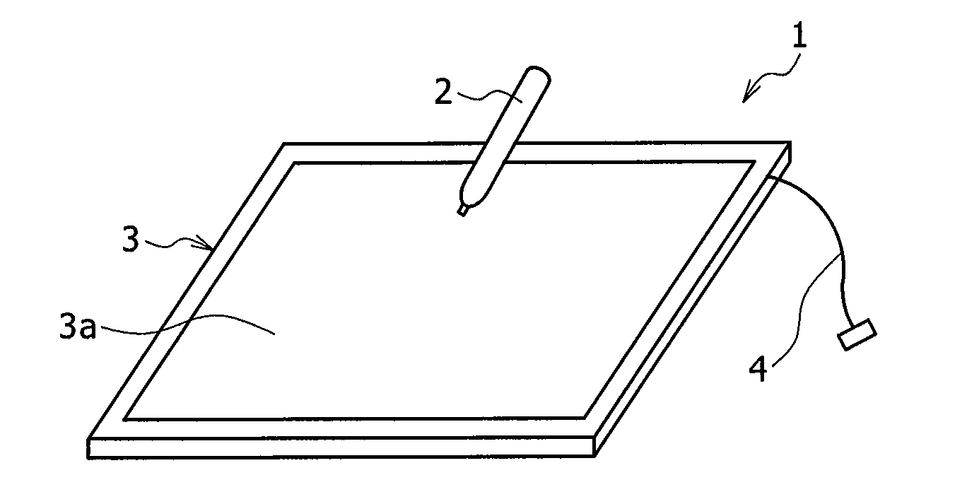
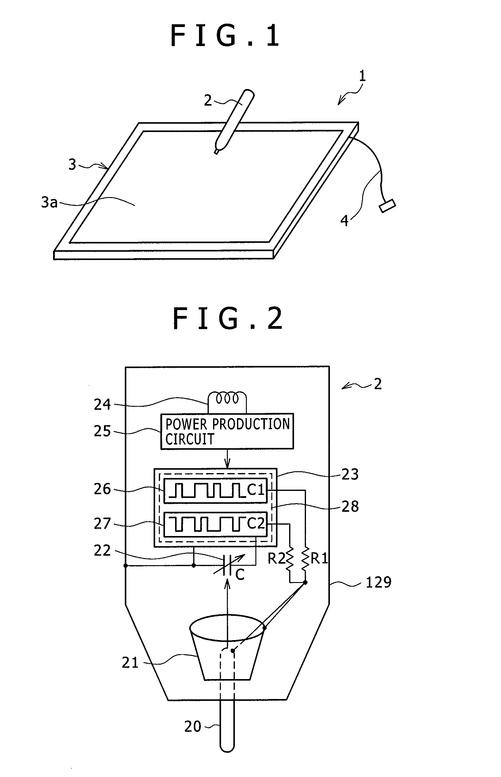
[0112]The pointer 110 illustrated in FIG. 12A includes a first electrode 20 having a shape of a rod, a cylindrical second electrode 21, a variable capacitor 22, an integrated circuit 111, a coil 24, a power production circuit 25, and a housing 129 which accommodates the components mentioned above. Further, the pointer 110 includes an operation switch provided at a part of a side face of the housing 129, to be operated by a finger or the like,...

modification 3

[Modification 3]

[0120]While, in the description of the embodiment and the modifications 1 and 2 described above, codes themselves from the pointer 2 are transmitted directly to the position detector 3, the present invention is not limited to this configuration. Predetermined modulation may be applied to spread codes, and the modulated codes (transmission codes) may be transmitted from the pointer 2 to the position detector 3. In the description of modification 3, a spread code is used as the first and second codes and is PSK (Phase Shift Keying) modulated.

[0121]FIGS. 13A and 13B show waveforms of a spread code before and after PSK modulation. FIG. 13A shows a waveform of a spread code before PSK modulation and FIG. 13B shows a waveform of the spread code after PSK modulation.

[0122]In this example, a spread code is PSK modulated with a signal having a clock period that is ½ the code period of the spread code before modulation. It is to be noted that the ratio between the clock period...


PUM


Abstract

A position detection apparatus of the electrostatic coupling type is provided, to detect not only a position of a pointer but also information other than the position information such as, for example, pointer pressure or side switch information. The pointer transmits two codes such that a pressure applied to a pen tip is associated with a time difference between the two codes. A position detector carries out a correlation matching operation between signals generated in reception conductors and correlation calculation codes corresponding to the two codes, to thereby detect a position on a sensor section pointed to by the pointer from a result of the correlation matching operation and based on at least one of the codes. The position detector further includes a pressure calculation circuit for detecting pressure applied to the pointer, which is associated with the time difference between the two codes, from the result of the correlation matching operation calculated by the correlation matching operation and based on the two codes.

Description

CROSS-REFERENCE TO RELATED APPLICATION[0001]The present application claims the benefit under 35 U.S.C. §119(a) of Japanese Application No. 2010-024858, filed Feb. 5, 2010, the entire content of which is incorporated herein by reference.TECHNICAL FIELD[0002]This invention relates to a pointer, a position detection apparatus and a position detection method, and more particularly to a pointer, a position detection apparatus and a position detection method of the electrostatic coupling type.BACKGROUND ART[0003]A position detection apparatus, called a tablet, has been developed as one of pointing devices used for producing an image or illustration on a computer apparatus. Such a position detection apparatus typically includes a position detector substantially in the form of a flat plate, and a pointer in the form of a pen to be operated by a user on the position detector.[0004]As such a position detection apparatus, for example, a position detection apparatus based on an electrostatic co...

Claims


Application Information

Patent Timeline
Patent Type & Authority Applications(United States)
IPC IPC(8): G06F3/041G06F3/033
CPCG06F3/046G06F3/044G06F3/03545G06F3/0446G06F3/04162G06F3/0442G06F3/0383G06F3/0416
Inventor ODA, YASUOYAMAMOTO, SADAOSUGIYAMA, YOSHIHISA
Owner WACOM CO LTD
Why Eureka
Try Eureka