Liquid crystal display device

a liquid crystal display and display device technology, applied in the field of liquid crystal display, can solve the problems of high temperature of the liquid crystal display device itself, uneven iridescence, and high birefringence of the polyester film, and achieve the effect of improving visibility

Active Publication Date: 2011-08-11
DAI NIPPON PRINTING CO LTD
View PDF19 Cites 39 Cited by
  • Summary
  • Abstract
  • Description
  • Claims
  • Application Information

AI Technical Summary

Benefits of technology

[0018]In the liquid crystal display of the invention, a polarizing plate having the specific optical properties is used as a polarizer-protective-film, so that an occurrence of iridescent unevenness can be prevented and that improved visibility can be provided.

Problems solved by technology

In addition, large-sized LCDs such as LCD televisions are required to have durability to higher temperature, because as their size and brightness increase, an amount of heat from the light source increases, so that the LCDs themselves tend to have high temperature.
However, the polyester film has high birefringence in the in-plane direction and the thickness direction, because its intrinsic birefringence is high and is highly stretched.
However, there is a problem in which when a polyester film is used as a protective film for the principal surface of the polarizer on the side not facing the liquid crystal cell in a polarizing plate placed on the light source side of a liquid crystal cell, iridescent unevenness (rainbow like unevenness) occurs to degrade visibility.
Particularly, as the brightness and color purity of LCDs have increased in recent years, such iridescent unevenness becomes more likely to be visible, which becomes a hindrance to the use of a polyester film as a polarizer-protective-film.
Such a method can make iridescent unevenness less visible but does not prevent iridescent unevenness itself, so that sufficient visibility cannot be obtained in some cases.
As the brightness and color purity of LCDs further increase, the occurrence of iridescent unevenness becomes more significant.
It is therefore considered that it will be difficult to ensure sufficient visibility by such a color mixing method for canceling iridescent unevenness.

Method used


Image

  • Liquid crystal display device
  • Liquid crystal display device
  • Liquid crystal display device

Examples


reference example 1

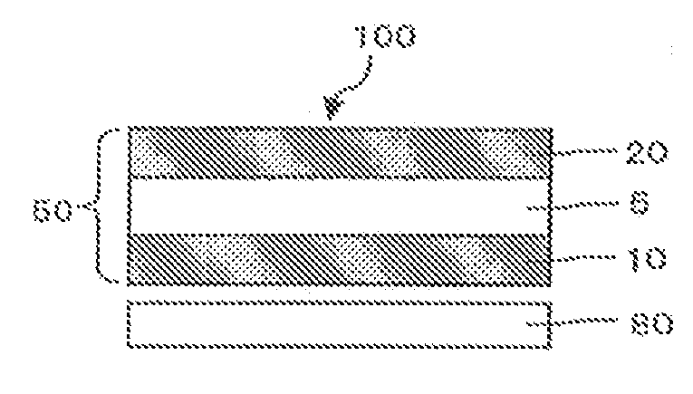
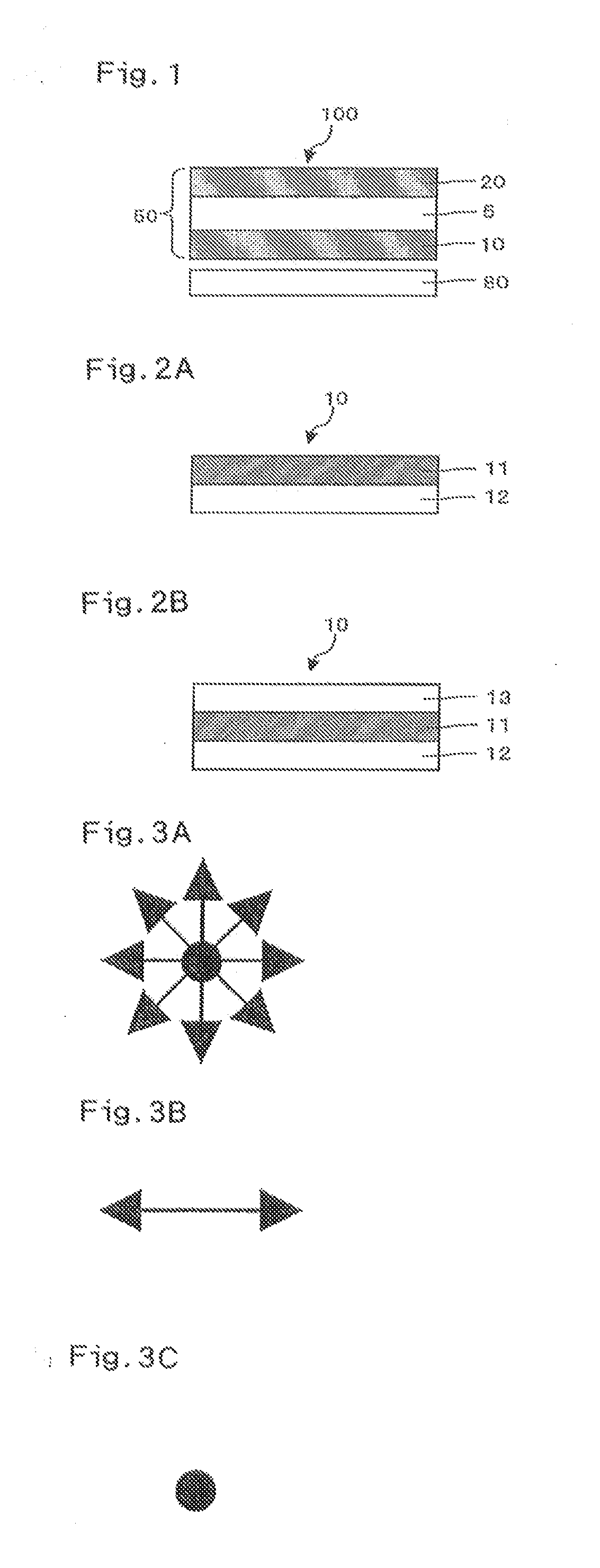
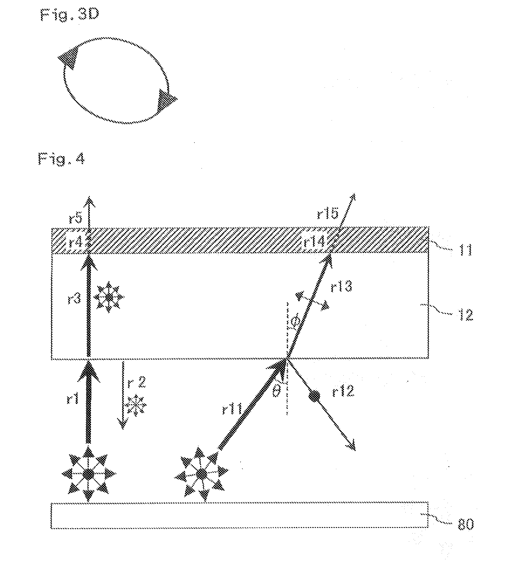
[0103]The same liquid crystal panel was used as that prepared in Example 1. The liquid crystal panel was incorporated into the original liquid crystal display, and in that process, a reflective, linearly-polarizing film (“D-BEF” (trade name) manufactured by 3M Company) comprising a laminate of alternating anisotropic thin films was placed between the liquid crystal panel and the light source in such a manner that the direction of its transmission axis was parallel to the direction of the transmission axis of the light source side polarizing plate B, so that a liquid crystal display was obtained. Then, whether or not iridescent unevenness occurred was visually evaluated as in the Examples.

[0104]Table 1 summarizes and shows the retardation properties of each protective film and the results of the evaluation of iridescent unevenness in the liquid crystal displays obtained in the Examples, the Comparative Examples, and the Reference Example. FIGS. 6 and 7 (photographs) show the display ...


PUM

PropertyMeasurementUnit
hazeaaaaaaaaaa
thickness directionaaaaaaaaaa
thickness direction retardation Rth1aaaaaaaaaa

Abstract

Provided is a liquid crystal display in which occurrence of iridescent unevenness is suppressed, even when a film with high level of mechanical properties, chemical resistance and water-barrier properties is used as a polarizer-protective-film. Also, disclosed is a polarizing plate to be used in the liquid crystal display. The liquid crystal display includes a liquid crystal cell, a light source, a first polarizing plate placed between the liquid crystal cell and the light source, and a second polarizing plate placed on a viewer side of the liquid crystal cell. The first polarizing plate includes a polarizer and a first protective film placed on a light source side principal surface of the first protective film, and the first protective film satisfies following relations: (i) 0 nm≦Re1≦3000 nm; (ii) Nz1≧5; and (iii) Rth1>2500 nm.

Description

FIELD OF THE INVENTION[0001]The invention relates to a liquid crystal display with high level of visibility.BACKGROUND ART[0002]A liquid crystal display (LCD), used in television, personal computer, mobile phone and the like, has a liquid crystal panel that includes a liquid crystal cell and polarizing plates placed on both sides of the liquid crystal cell so that it enables display by controlling an amount of transmission of light emitted from a light source. As LCDs have been rapidly developed, their functions and applications tend to be diversified, and they are required to withstand more harsh environments during use. For example, LCDs for mobile applications such as cellular phones and for vehicle applications such as car navigation systems are required to have durability even to more harsh environments during use. In addition, large-sized LCDs such as LCD televisions are required to have durability to higher temperature, because as their size and brightness increase, an amount...

Claims


Application Information

Patent Timeline
Patent Type & Authority Applications(United States)
IPC IPC(8): G02F1/1335G02B5/30
CPCG02B1/105G02B5/3033G02F2001/133635G02F1/133528G02B5/3083G02B1/14G02F1/133635G02F1/13363G02F1/1335G02B5/30
Inventor IZAKI, AKINORIUMEMOTO, SEIJIYAMAMOTO, SHOUJITAKEDA, KENTAROUSUZUKI, MITSURU
Owner DAI NIPPON PRINTING CO LTD
Why Eureka
Try Eureka