Calibration of a lens device

a technology of lens and calibration, which is applied in the field of camera devices, can solve the problems of inability to develop a control algorithm for controlling the optical performance of the camera, inconvenient environment, and inability to use the camera or the user, so as to facilitate the procedure of making parameters, and reduce the effect of one or two

Active Publication Date: 2011-08-11
AXIS
View PDF7 Cites 28 Cited by
  • Summary
  • Abstract
  • Description
  • Claims
  • Application Information

AI Technical Summary

Benefits of technology

[0017]With the above and following description in mind, an aspect of the present invention is to provide a way to facilitate the procedure of making the parameters of the P-Iris lens available to the camera, and thus mitigate, alleviate, or eliminate one or more of the above-identified deficiencies in the art and disadvantages singly or in any combination.

Problems solved by technology

This is not convenient in an environment with changing light conditions such as outdoors.
However, the main difference between the two types is where the circuitry for converting the analog signal into motor control signals is located.
This problem is especially prominent in cameras with high resolution image sensors where the pixel size of the image sensor may be close to the diffraction limit of the camera optics.
The problem with conventional automatic iris lenses is that the control is not available to the camera or to the user of the camera.
This is a severe disadvantage since it in this way makes it impossible to develop a control algorithm for controlling the optical performance of the camera.
The depth of field, the resolution and the effect of optical aberration are also affected by not being able to control the absolute position of the iris opening.
However, this inept way of manually having to make the parameters available to the camera can be quite tedious and time-consuming.

Method used


Image

  • Calibration of a lens device
  • Calibration of a lens device
  • Calibration of a lens device

Examples


first embodiment

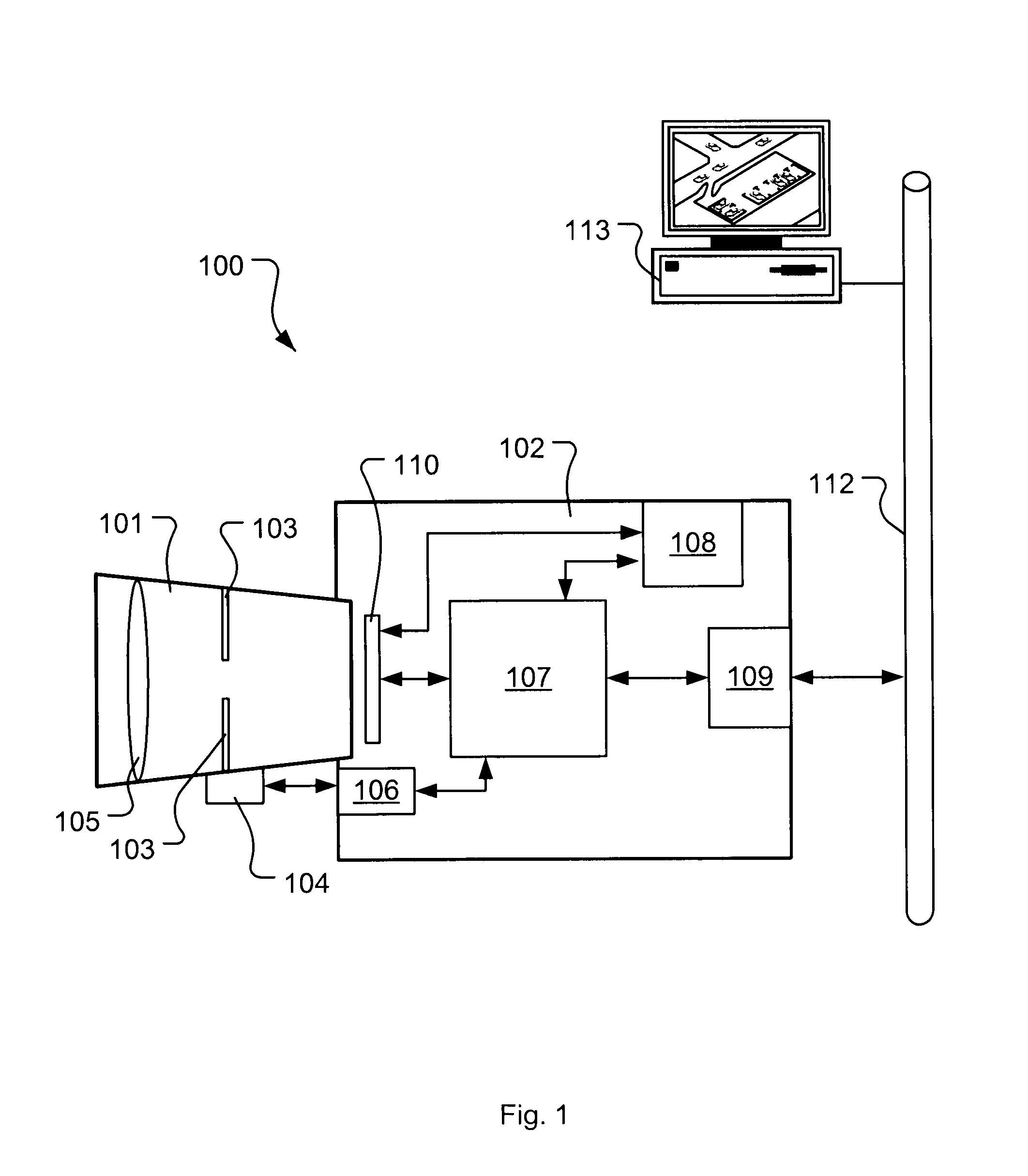
[0071]In the present invention the high frequency content in a recorded image is determined by the processing means 107 using for instance a Sobel algorithm (i.e. discrete differentiation operator) and a Gaussian filter. The analysis of the high frequency content may result in a single value, from hereinafter referred to as a high frequency value (HF value), representing the amount of high frequency information that is present in a recorded image at the current position of the iris. The determined HF value may be stored in the memory 108. In a variant, a series of HF values are derived from a series of recorded images recorded at the same iris position. The series of HF values are then, for example, averaged into a single HF value. The averaging of a series of HF values will reduce the amount of noise and the negative effect of fast variations of the light in a scene, resulting in a more accurate HF value.

second embodiment

[0072]In a second embodiment the amount of light in an image may be determined. When arriving at a position the exposure algorithm will compensate for the light impinging on the image sensor 110 by adjusting the exposure time (i.e. integration time) and / or the gain of the image sensor 110. When the adjustment is done the value of the exposure time and the value of the gain of the image sensor 110 are stored in the memory 108. If multiple images have been recorded the average exposure time value and average gain value may be stored in the memory 108. In a variant the light intensity of the image is determined and stored in the memory 108. The light intensity of the current image may then be compared to the light intensity coming from at least one previously recorded image. The difference in light intensity between the two images may give information about if a stepping motor end position (closed or fully open) is reached or is close to be reached. It may also give information about i...

third embodiment

[0073]In a third embodiment the HF value and the values of the exposure time and the gain of the image sensor 110 is determined and stored in the memory 108. If multiple images have been recorded the respective averaged values may be stored in the memory 108.

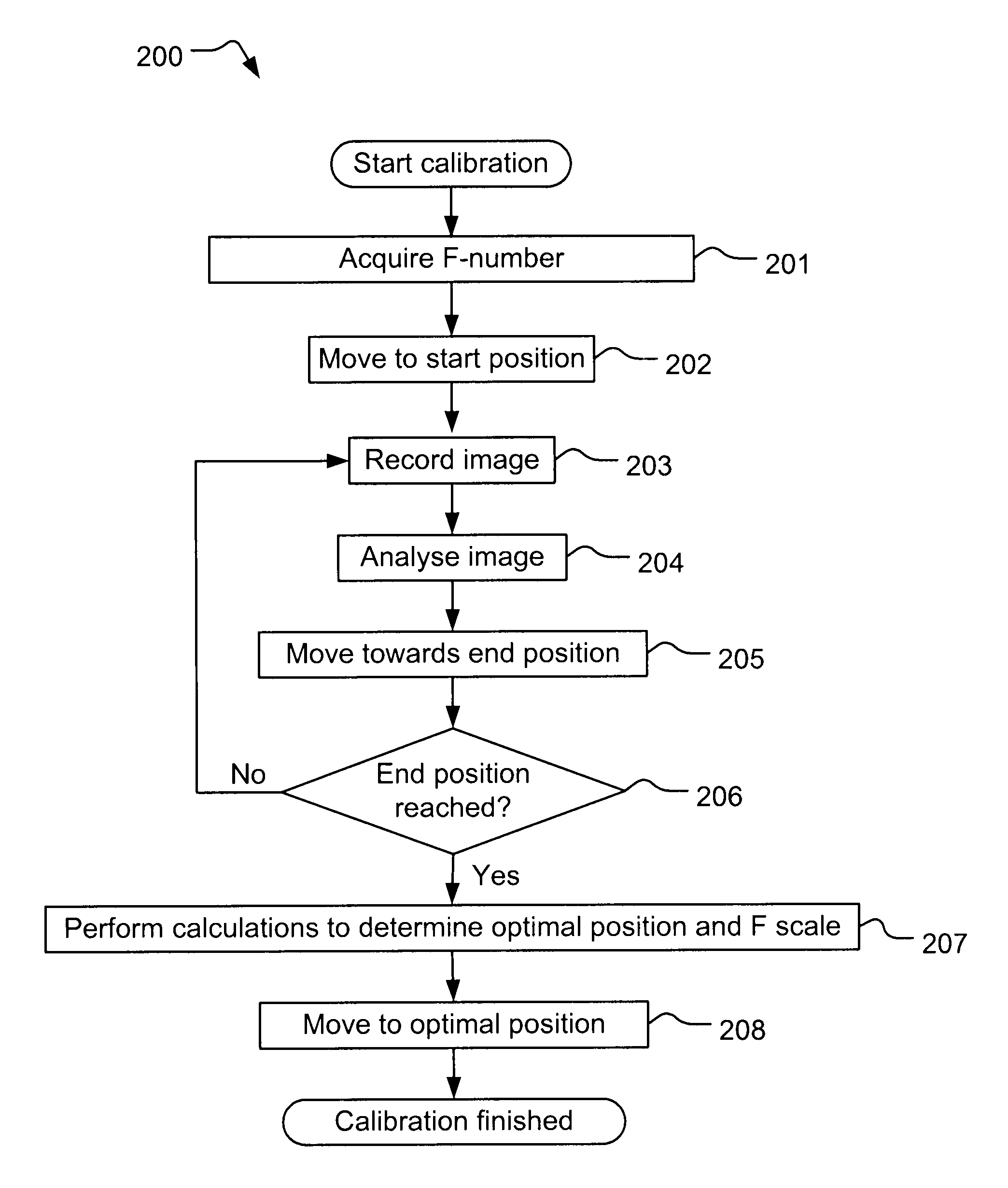
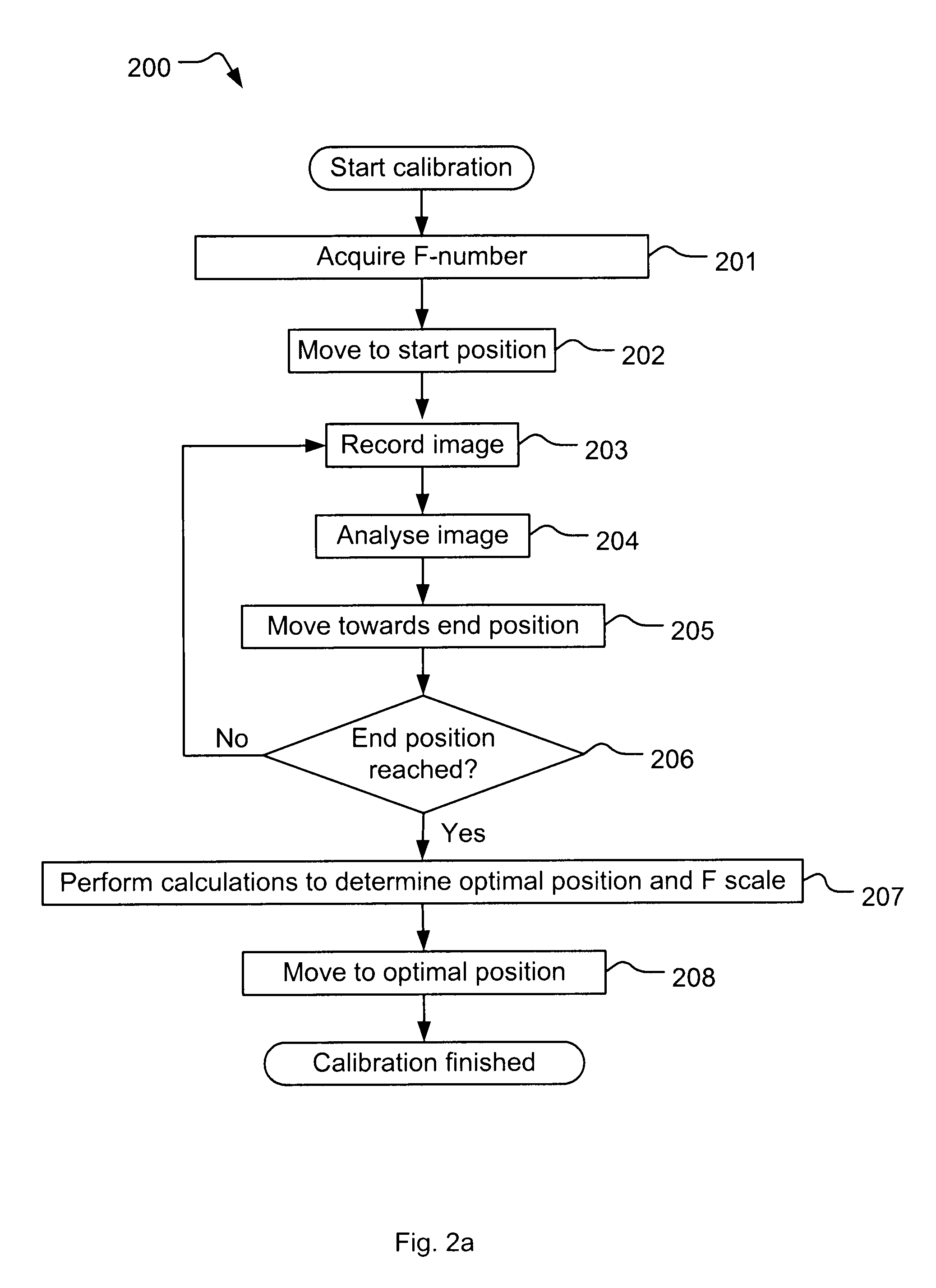
[0074]In flowchart step 205 of the calibration the stepping motor is moved one or more steps towards an end position. In one embodiment the stepping motor moves one (or several) step in the direction of closing the iris opening by moving the diaphragm blades 103 of the P-Iris 101 closer to each other. In yet another embodiment the stepping motor moves one (or several) step in the direction of opening the iris opening by moving the diaphragm blades 103 of the P-Iris 101 further apart from each other.

[0075]In flowchart step 206 of the calibration it is determined if an end position is reached or not. If the end position is not reached the steps: ‘record image’203, ‘analyse image’204, and ‘move towards end position’205 is repeated ...


PUM


Abstract

The invention relates to a calibration method in a camera with a P-Iris lens having an adjustable iris opening. The calibration comprise the steps of adjusting the size of the iris opening between a first opening position and a second opening position, recording a plurality of images during the adjusting, analyzing the images, and determining an iris opening, based on the analysis, that obtains a high quality image

Description

CROSS-REFERENCE TO RELATED APPLICATIONS[0001]This application is related to and claims priority under 35 U.S.C. §119 (e) to Provisional Application Ser. No. 61 / 304,124, filed Feb. 12, 2010, and also claims the benefit of priority to European Patent Application No. 10153060, filed on Feb. 9, 2010, the contents of both of which are incorporated herein by reference.TECHNICAL FIELD[0002]The present invention relates to the field of camera devices and, in particularly, to the calibration of a camera with a lens having an adjustable iris opening.BACKGROUND OF THE INVENTION[0003]The ability to control an iris opening of a camera lens plays an important role in image quality. An iris is used to maintain the optimal light level to the image sensor in the camera so that the image can be sharp, clear and correctly exposed with good contrast and resolution. The iris can also be used to control the depth of field in the image.[0004]The iris opening can either be fixed or adjustable. The opening ...

Claims


Application Information

Patent Timeline
Patent Type & Authority Applications(United States)
IPC IPC(8): G03B7/08
CPCG03B7/095H04N17/002G03B43/00H04N23/75G03B7/08G03B7/091
Inventor HJELMSTROM, JONAS
Owner AXIS
Why Eureka
Try Eureka