Prismatic sealed secondary cell and method of manufacturing the same

Active Publication Date: 2011-08-11
SANYO ELECTRIC CO LTD
View PDF17 Cites 25 Cited by
  • Summary
  • Abstract
  • Description
  • Claims
  • Application Information

AI Technical Summary

Benefits of technology

[0066]As mentioned above, according to the invention, there can be provided a prismatic sealed secondary cell

Problems solved by technology

However, because a thin electrode core may be easily broken and result in an electrica

Method used


Image

  • Prismatic sealed secondary cell and method of manufacturing the same
  • Prismatic sealed secondary cell and method of manufacturing the same
  • Prismatic sealed secondary cell and method of manufacturing the same

Examples


embodiment 1

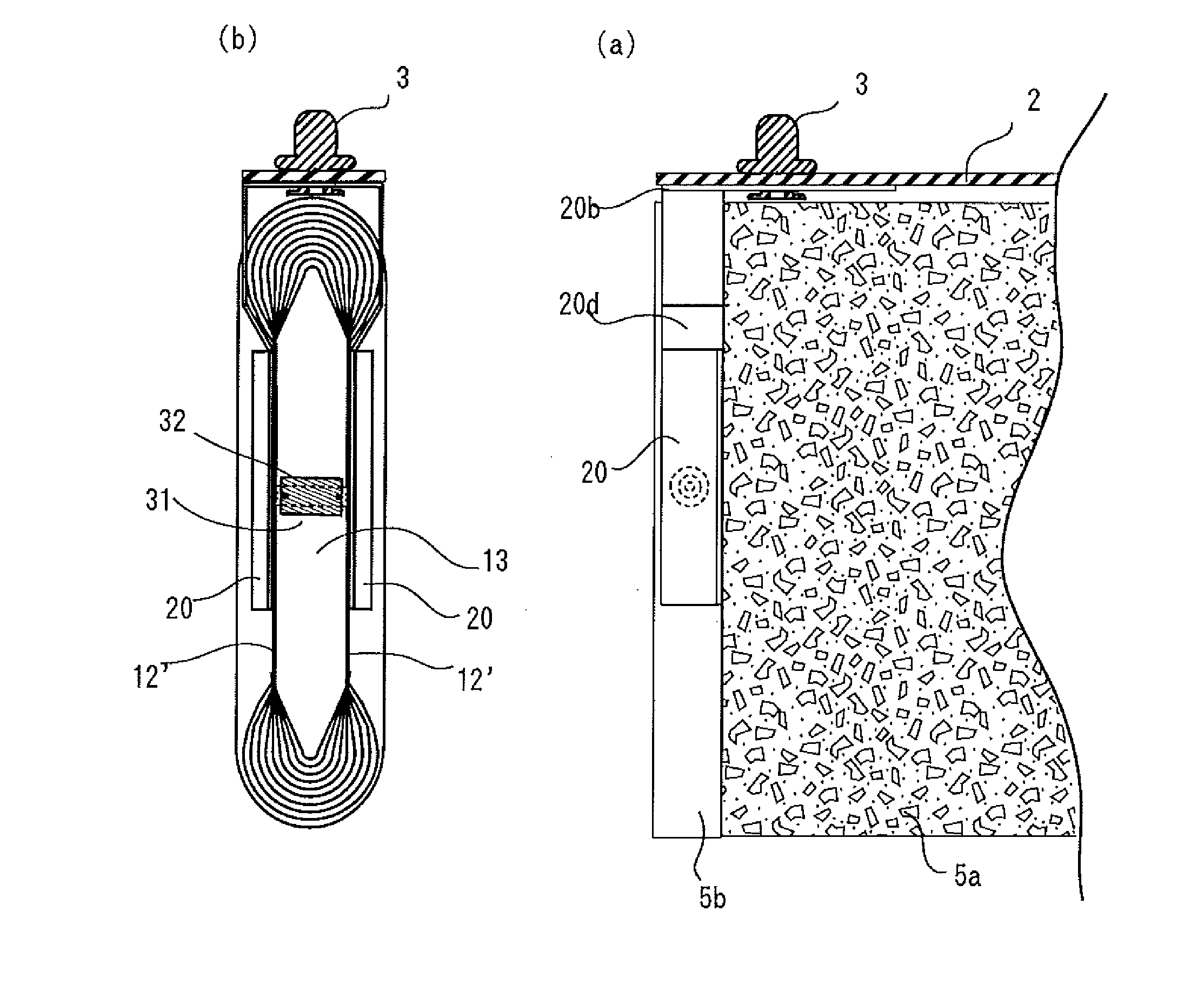
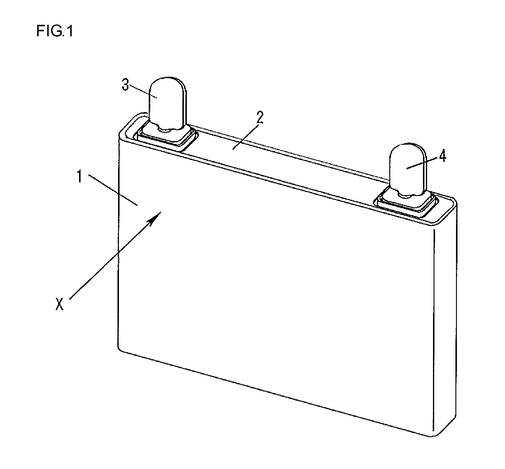
[0080]An Embodiment for carrying out the present invention will be explained using as an example of a lithium ion secondary cell using a spiral flat electrode assembly. FIG. 1 is a perspective view showing the appearance of a lithium ion secondary cell (prismatic sealed secondary cell) using a spiral flat electrode assembly. As shown in FIG. 1, the lithium ion secondary cell according to Embodiment 1 comprises a prismatic cell case 1, a sealing plate 2 for sealing an opening of the prismatic cell case 1, and positive and negative electrode external output terminals 3 and 4 outwardly protruding from the sealing plate 2. In addition, a spiral flat electrode assembly 10 as a main component is housed in the prismatic cell case 1.

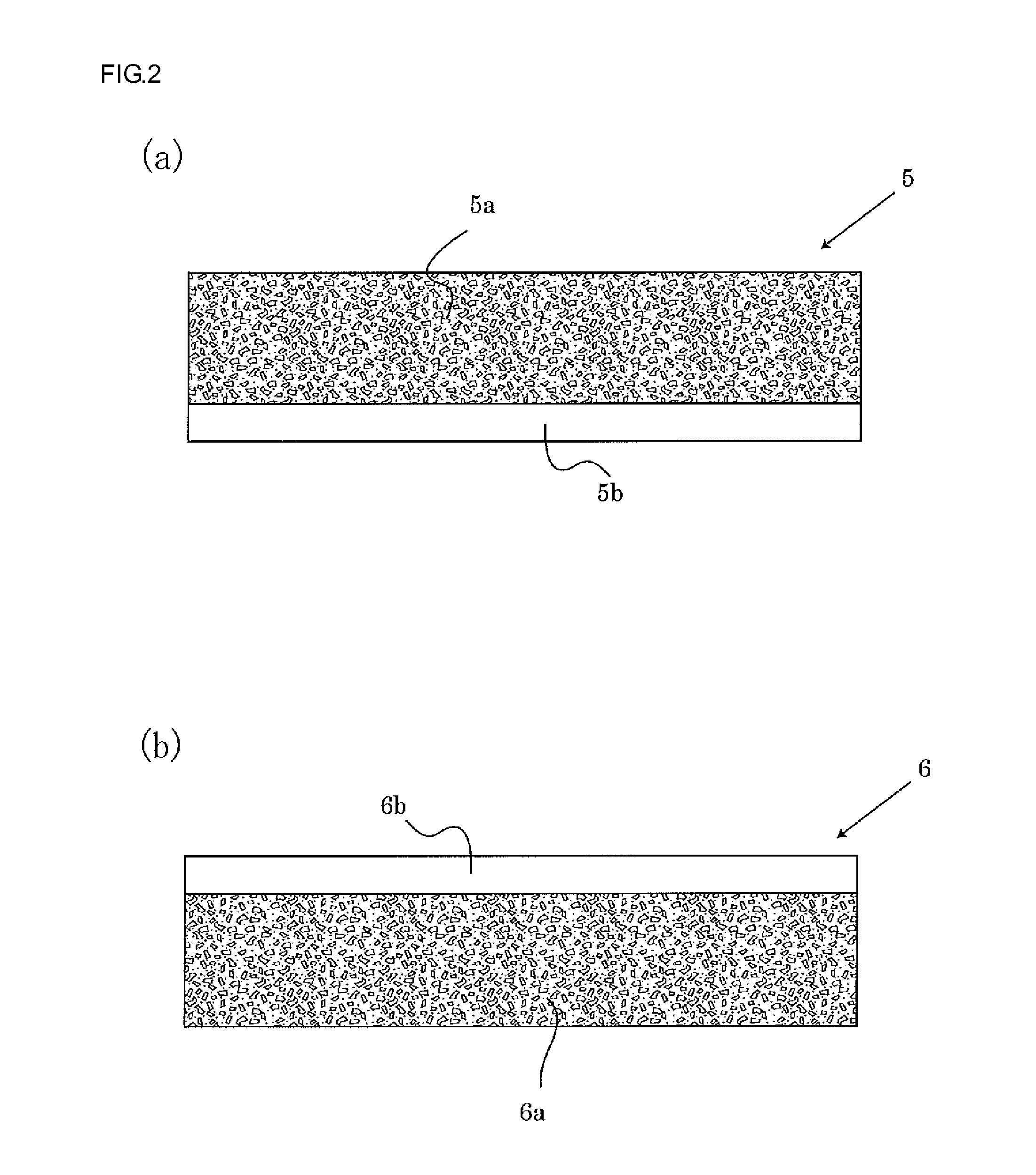
[0081]FIG. 2 shows a front view schematically depicting the positive and negative electrode plates used in the lithium ion secondary cell according to Embodiment 1. In this drawing, FIG. 2(a) shows a positive electrode plate 5, and FIG. 2(b) shows a negative ele...


PUM

PropertyMeasurementUnit
Fractionaaaaaaaaaa
Thicknessaaaaaaaaaa
Electrical conductoraaaaaaaaaa

Abstract

The present invention provides a prismatic sealed secondary cell that is excellent in current collection efficiency and current collection stability, and capable of high output discharge.
In the prismatic sealed secondary cell in which a laminate-type or a wound laminate-type of flat electrode assembly is housed in a prismatic cell case, a pair of current collector plates are disposed on a flat portion of the outermost surface of the core exposed portion 5b of the first electrode plate constituting the flat electrode assembly so that the pair of current collector plates sandwich the flat portion in the thickness direction, and a columnar connection conductive member is interposed between two-divided core exposed portion laminates in the flat portion sandwiched between the pair of current collector plates, and the pair of current collector plates, the columnar connection conductive member and the two-divided core exposed portion laminates are welded to each other.

Description

BACKGROUND OF THE INVENTION[0001]1. Field of the Invention[0002]The present invention relates to a current collector system structure to increase stability in current collection of a prismatic sealed secondary cell.[0003]2. Background Art[0004]In recent years, a cell-powered car using a secondary cell as a power source, such as an electric vehicle (EV) and a hybrid electric vehicle (HEV), has been becoming popular. However, a high power secondary cell is required for such a cell-powered vehicle. In addition, since sophistication of mobile electronic devices such as mobile phones and laptop computers is developing, higher output of cells is also required in these applications.[0005]To obtain high output from a cell, it is necessary to increase a facing area between positive and negative electrodes of the cell. The facing area between the electrodes can be increased using a laminated electrode assembly in which a number of positive and negative electrode plates are laminated or a spir...

Claims


Application Information

Patent Timeline
IPC IPC(8): H01M2/26H01M10/36H01M4/04H01M10/04H01M50/538
CPCH01M10/052Y02E60/122H01M2/263Y02T10/7011Y10T29/49115H01M2/0217H01M10/0587H01M10/0585Y10T29/49108H01M10/0431Y02E60/10H01M50/103H01M50/538Y02P70/50Y02T10/70H01M50/54H01M50/543
Inventor KAMIFUJI, TAIKIKIMURA, TAKENORIYAMAMOTO, KOUSUKE
Owner SANYO ELECTRIC CO LTD
Why Eureka
Try Eureka