Methods and devices for sensing respiration and controlling ventilator functions

a technology of respiration sensor and function, applied in the field of ventilation therapy, can solve the problems of poor synchrony, sensor during that time no longer measuring the respiration of the patient but rather the activity of the ventilator, and breath sensor in-line with the ventilation gas delivery circuit can be ineffective in measuring the entire respiratory pattern, so as to reduce the resistance to upper airway breathing

Active Publication Date: 2011-08-18
BREATHE TECHNOLOGIES INC
View PDF0 Cites 68 Cited by
  • Summary
  • Abstract
  • Description
  • Claims
  • Application Information

AI Technical Summary

Problems solved by technology

In-line breath sensors are also used to measure the entire respiratory curve in addition to just the start of inspiration; however, because the gas being delivered by the ventilator also moves past the sensor, the sensor during that time no longer measures the patient's respiration but rather the ventilator activity.
In this case, a breath sensor in-line with the ventilation gas delivery circuit can be ineffective in measuring the entire respiratory pattern.
However, poor synchrony is still reported in some cases because of the demanding and exacting task of measuring all the different possible spontaneous breathing signals and the vast range of variations that exist.
However, this approach is technically challenging because the signal is prone to drift, noise and artifacts caused by patient motion and abdominal movement.
However, this technique requires an additional invasive device and sensor, and does not monitor exhalation activity since that is a neurally passive function.
While an improvement over conventional triggering techniques in conventional ventilation, this technique still has disadvantages and in fact has not yet been converted into commercial practice.
Also, existing systems have a logistically cumbersome interface with the external control system.
In summary, existing systems have the one or more of the following disadvantages that require improvement: (1) they do not measure the complete breath cycle, (2) the are in-line with the channel used for ventilation gas delivery, (3) they have a limited range of accuracy and sensitivity, and (4) they are logistically cumbersome to interface with the ventilator.

Method used


Image

  • Methods and devices for sensing respiration and controlling ventilator functions
  • Methods and devices for sensing respiration and controlling ventilator functions
  • Methods and devices for sensing respiration and controlling ventilator functions

Examples


Embodiment Construction

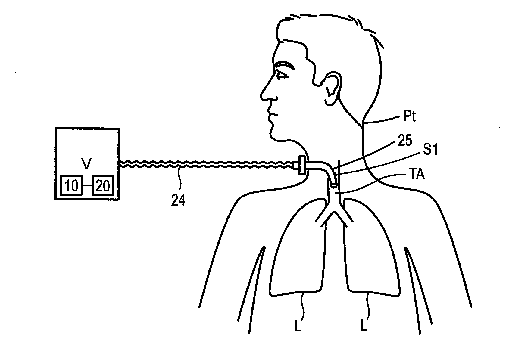
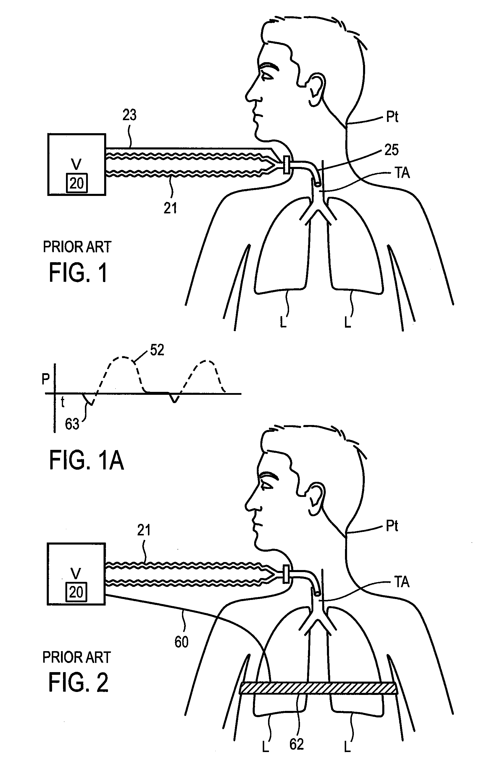
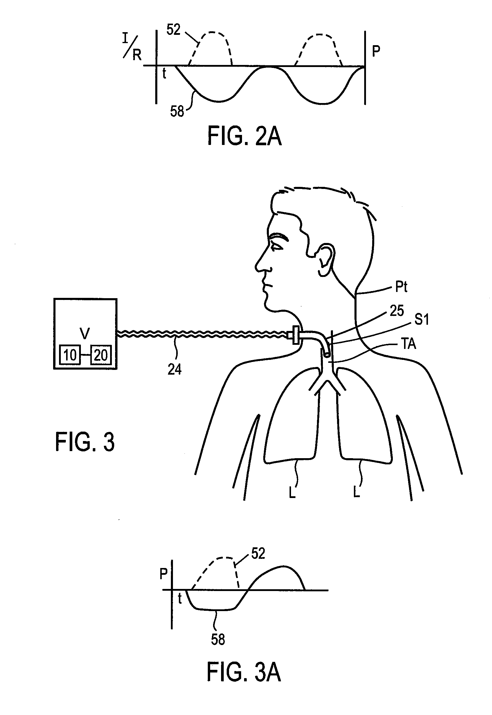
[0102]FIG. 1 (prior art) describes a conventional ventilator system in which the breath sensor is in line with the ventilation gas being delivered in the breathing circuit. The Ventilator V delivers gas to the patient Pt through the ventilation gas delivery circuit, dual limb 21 and ventilation tube 25. A pressure tap 23 in series or in line with the ventilator gas flow senses a negative pressure created by a patient inspiratory effort. Alternatively, a flow sensor can be used in series with the ventilation circuit to detect when the patient inspires. The signal from the breath sensor is delivered to a ventilator control unit 20 in the ventilator V. As seen in FIG. 1a these in-series sensor systems measure the start of a patient inspiratory effort 63, but after the ventilator V is triggered to deliver a mechanical breath to the patient Pt, the sensor signal predominantly indicates the ventilator activity in the form of a ventilator gas delivery pressure tracing 52, and not the patie...


PUM


Abstract

Improved methods and devices are described for sensing the respiration pattern of a patient and controlling ventilator functions, particularly for use in an open ventilation system. A ventilation and breath sensing apparatus may include a ventilation gas delivery circuit and a ventilation tube coupled to the ventilation gas delivery circuit. A plurality of pressure sensing elements may be separated by a distance and may produce independent signals. The signals may be used to detect pressure differentials between the plurality of pressure sensing elements. Sensing ports may be located in an airway, and connected to transducers that are valved to optimize sensitivity and overpressure protection. Airway pressure and flow can both be obtained and used to optimize ventilator synchronization and therapy.

Description

CROSS-REFERENCE TO RELATED APPLICATIONS[0001]This application claims priority to U.S. Provisional Patent Application No. 61 / 071,252, entitled “Methods and Devices for Sensing Respiration and Controlling Ventilator Functions”, filed Apr. 18, 2008, the content of which is incorporated by reference in its entirety.[0002]This application incorporates by reference in their entireties: U.S. patent application Ser. No. 10 / 870,849, entitled “Methods, Systems and Devices for Improving Ventilation in a Lung Area”, filed Jun. 17, 2004; U.S. patent application Ser. No. 12 / 153,423, entitled “Methods and Devices for Sensing Respiration and Providing Ventilation Therapy”, filed May 19, 2008; U.S. patent application Ser. No. 10 / 771,803, entitled “Method and Arrangement for Respiratory Support for a Patient Airway Prosthesis and Catheter”, filed Feb. 4, 2004; U.S. patent application Ser. No. 11 / 523,518, entitled “Systems, Methods and Apparatus for Respiratory Support of a Patient”, filed Sep. 20, 20...

Claims


Application Information

Patent Timeline
Patent Type & Authority Applications(United States)
IPC IPC(8): A61M16/00
CPCA61B5/03A61B5/085A61B5/087A61M2205/17A61M16/0465A61M2016/0015A61M16/00A61M16/1055A61M16/106A61M2016/0413A61M16/0858A61M16/0051A61M16/026A61M16/0427A61M16/0475A61M16/1045
Inventor WONDKA, ANTHONY D.BRYAN, ROBERT F.MCCALL, MARKTRAN, CUONG Q.
Owner BREATHE TECHNOLOGIES INC
Why Eureka
Try Eureka