Non-contact dancer mechanisms, web isolation apparatuses and methods for using the same

a non-contact, dancer technology, applied in the direction of glass drawing apparatus, dough-sheeter/rolling machine/rolling pin, rotary bearing, etc., can solve the problems of difficult control and synchronization of multiple processes, adverse influence on the drawing process, and uncoated thin glass ribbons are particularly susceptible to damage, so as to prevent mechanical contact and damage to the web

a non-contact, dancer technology, applied in the direction of glass drawing apparatus, dough-sheeter/rolling machine/rolling pin, rotary bearing, etc., can solve the problems of difficult control and synchronization of multiple processes, adverse influence on the drawing process, and uncoated thin glass ribbons are particularly susceptible to damage, so as to prevent mechanical contact and damage to the web

US20110198378A1Inactive Publication Date: 2011-08-18CORNING INC

Image

  • Non-contact dancer mechanisms, web isolation apparatuses and methods for using the same
  • Non-contact dancer mechanisms, web isolation apparatuses and methods for using the same
  • Non-contact dancer mechanisms, web isolation apparatuses and methods for using the same

Examples


Embodiment Construction

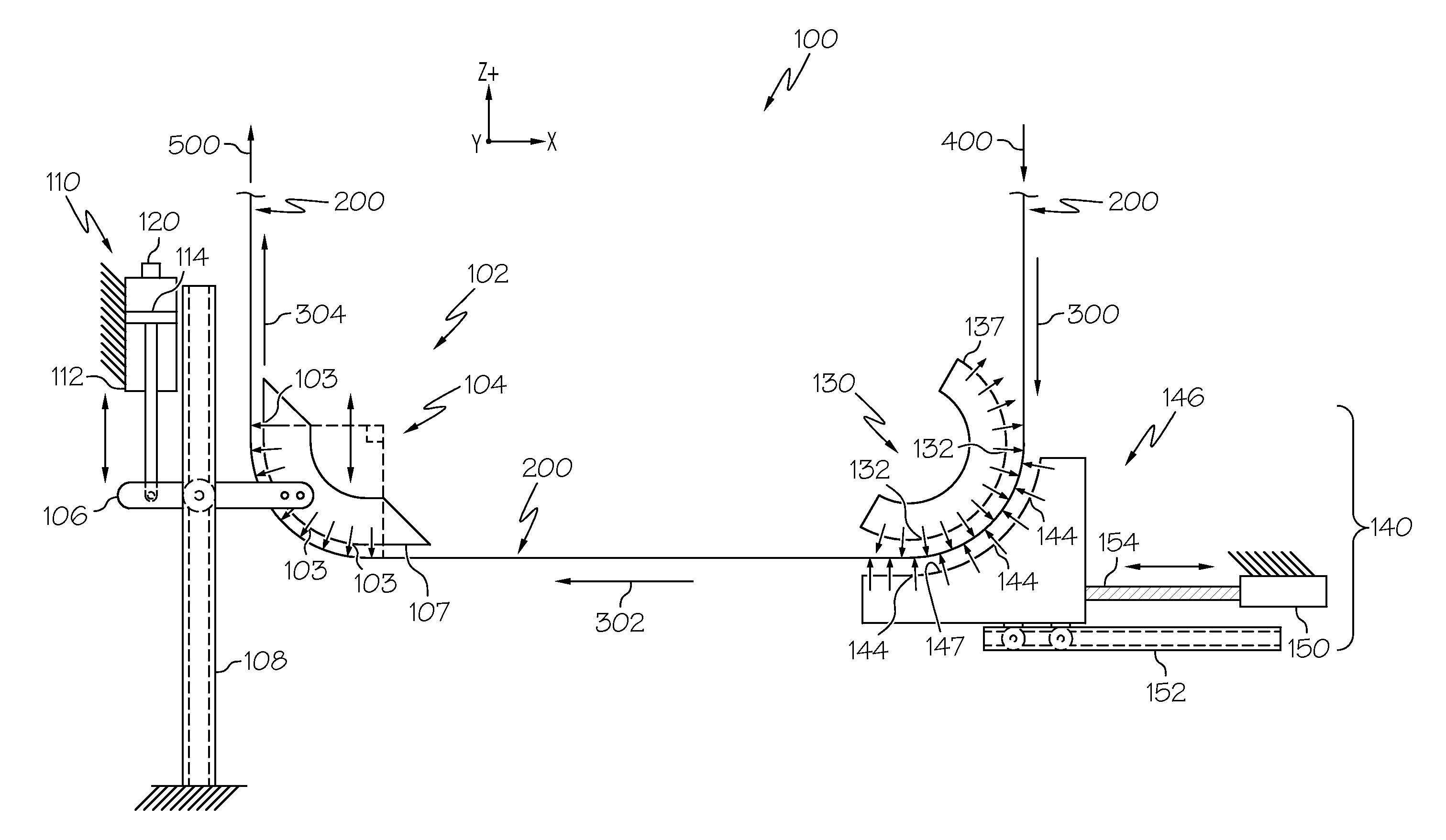
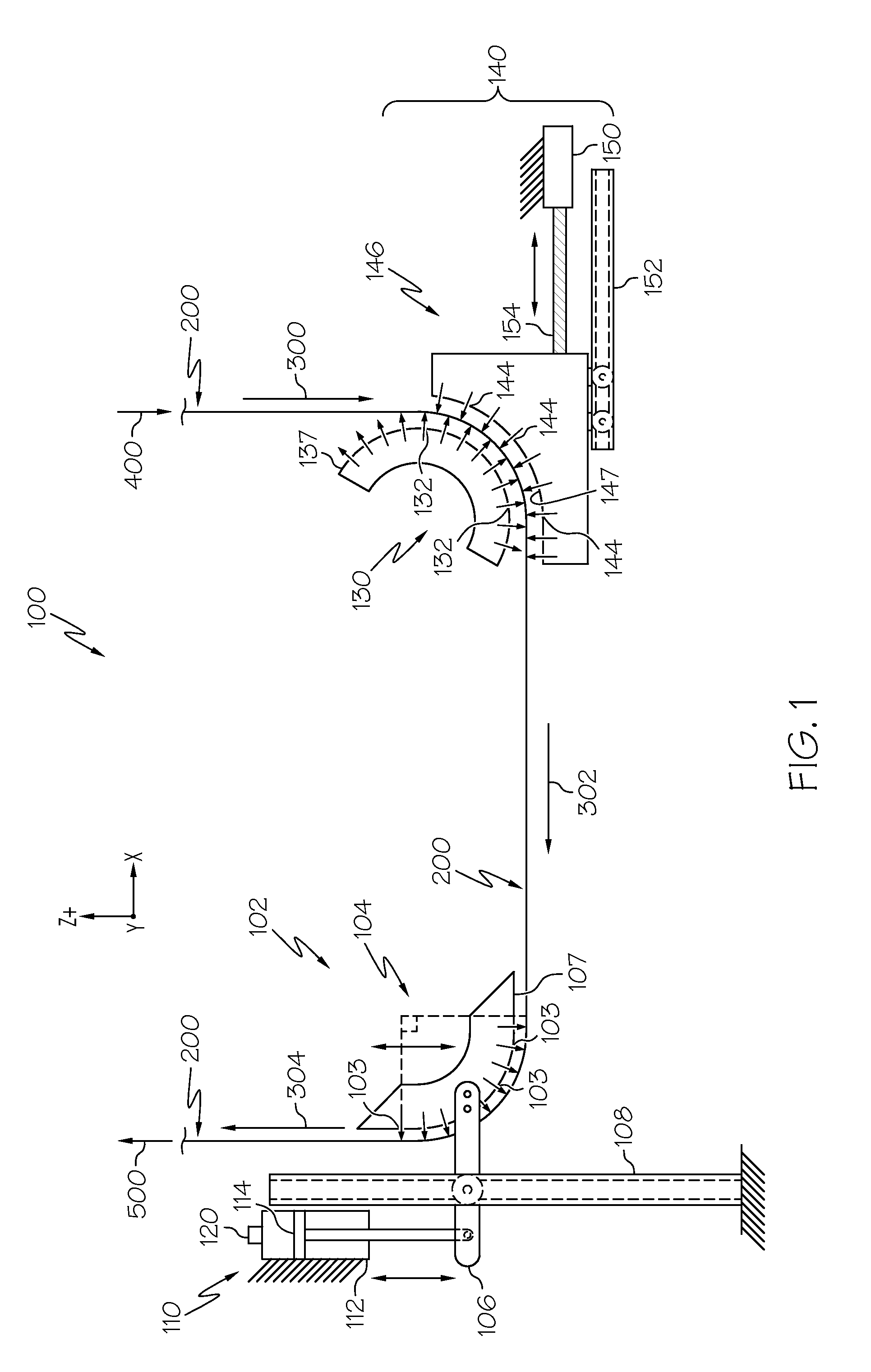
[0017]Reference will now be made in detail to various embodiments of web isolation apparatuses, examples of which are illustrated in the accompanying drawings. Whenever possible, the same reference numerals will be used throughout the drawings to refer to the same or like parts. One embodiment of a web isolation apparatus is schematically depicted in FIG. 1. The web isolation apparatus generally includes a fixed position web support plenum and a non-contact dancer mechanism. The non-contact dancer mechanism redirects a web of brittle material from a first pathway to a second pathway thereby isolating upstream and downstream processes from one another. This redirection reduces the impact of process rate differences in the upstream and downstream processes. One or more process parameters of the upstream process and / or the downstream process may also be adjusted based on the position of the non-contact dancer mechanism. Various components of the web isolation systems and the operation ...


PUM

PropertyMeasurementUnit
Weightaaaaaaaaaa
Radiusaaaaaaaaaa
Brittlenessaaaaaaaaaa

Abstract

A non-contact dancer mechanism for conveying a web of brittle material includes a guide rail and a variable position web support plenum adjustably positioned on the guide rail. The variable position web support plenum may include an arcuate outer surface with a plurality of fluid vents for emitting a fluid to support the web of brittle material over and spaced apart from the arcuate outer surface thereby preventing mechanical contact and damage to the web of brittle material. A support plenum counterbalance may be mechanically coupled to the variable position web support plenum, wherein the support plenum counterbalance supports at least a portion of the weight of the variable position web support plenum on the guide rail. Apparatuses incorporating the non-contact dancer mechanism and methods for using the non-contact dancer mechanism for handling continuous webs of brittle material are also disclosed.

Description

BACKGROUND[0001]1. Field[0002]The present specification generally relates to the manufacture and processing of webs of brittle material and, more specifically, to apparatuses with non-contact dancer mechanisms and methods for using the same to convey webs of brittle material.[0003]2. Technical Background[0004]Thin glass ribbons may be formed by processes such as the fusion process or other, similar downdraw processes. Such thin glass ribbons can be used in a variety of devices including flat panel displays, touch sensors, photovoltaic devices and other electronic applications. The fusion process yields thin glass ribbons which have surfaces with superior flatness and smoothness when compared to glass ribbons produced by other methods.[0005]In the fusion process, a fusion draw machine (FDM) is used to form a glass ribbon and stretch the glass ribbon to a desired thickness by drawing the glass ribbon between two sets of rolls. For example, the fusion draw process may be used to draw t...

Claims


Application Information

Patent Timeline
18 Aug 2011
Publication
US20110198378A1
IPC
B65H20/14
CPC
B65H20/14; B65G49/065; B65G49/063; B65H20/10; B65H23/10; B65H23/188; B65H23/24; B65H43/00
Inventors
CHANG, CHESTER H.H.; COLE, KEVIN A