
Vehicle capable of driving on land, air or water

a technology for transporting vehicles and airliners, applied in the field of transporting vehicles, can solve the problems of low energy efficiency of fixed-wing aircraft in producing lift or forward thrust, usually needs a long track, and can not be easily adapted to the needs of fixed-wing aircra

Inactive Publication Date: 2011-08-18
LIU GUOWEN +2
View PDF21 Cites 7 Cited by
  • Summary
  • Abstract
  • Description
  • Claims
  • Application Information

AI Technical Summary

Benefits of technology

[0006]A primary object of the present invention is to provide a vehicle that not only has the advantage of taking off and landing vertically as a helicopter, but also can gain lift and forward thrust in a more reasonable and scientific way. Different from a helicopter, which rotates its tilted blades in a horizontal plane or in a conical surface close to a horizontal plane, the vehicle provided by the present invention rotates its straight flat blades in vertical or nearly vertical planes.

Problems solved by technology

Therefore, a fixed-wing aircraft usually needs a long track to take off.
Similarly, since when its speed is too low it cannot get enough lift and will start to fall quickly.
In addition, a fixed-wing aircraft also has low energy efficiency in producing lift or forward thrust.
However, helicopters also have some disadvantages, such as low energy efficiency, loud noise and low loading capacity.
These disadvantages result from the working principle of theirs rotary blades in producing thrust.
This horizontal resistant force wastes energy.
However, reducing this angle will reduce the air-attacking area and air-attacking speed of the blade, causing a reduction of lift.
However, the rotation speed of the engine cannot be increased unlimitedly and, a large increase of the rotation speed of the blade also causes a rapid increase of many kinds of frictions and resistances (mechanically and from the air), thus resulting in energy wastes from other sources.
An increase of the rotation speed of the blade also causes an increase of noise.
Therefore, theoretically, helicopters can neither increase their energy efficiency by reducing energy waste, nor reduce their noise.
In this manner, a helicopter can gain forward thrust, but at the cost of some upward thrust.
In this condition, to maintain its original lift, the helicopter has to either increase the angle between its blades and a horizontal plane or to increase the rotation speed of its blades, both reducing its energy efficiency in producing thrust.
Therefore, under a fixed power of its engine, if a helicopter wants to fly in a high speed, it will have to reduce its load, thus having its speed and load both limited.

Method used


Image

  • Vehicle capable of driving on land, air or water
  • Vehicle capable of driving on land, air or water
  • Vehicle capable of driving on land, air or water

Examples


Embodiment Construction

[0006]A primary object of the present invention is to provide a vehicle that not only has the advantage of taking off and landing vertically as a helicopter, but also can gain lift and forward thrust in a more reasonable and scientific way. Different from a helicopter, which rotates its tilted blades in a horizontal plane or in a conical surface close to a horizontal plane, the vehicle provided by the present invention rotates its straight flat blades in vertical or nearly vertical planes.

[0007]The present invention is achieved as: a vehicle capable of moving on land, in air and / or in water, comprises at least a fuselage, a main engine or main electric engine and a power control and transmitting system. On both sides of the fuselage there are main shafts stretching out. The main shafts have blade sleeves fixed on them. Blade sleeves have blade handles installed in / on them in a way that the blade handles can spin around their own central axes. On blade handles there are blades fixed ...


PUM


Abstract

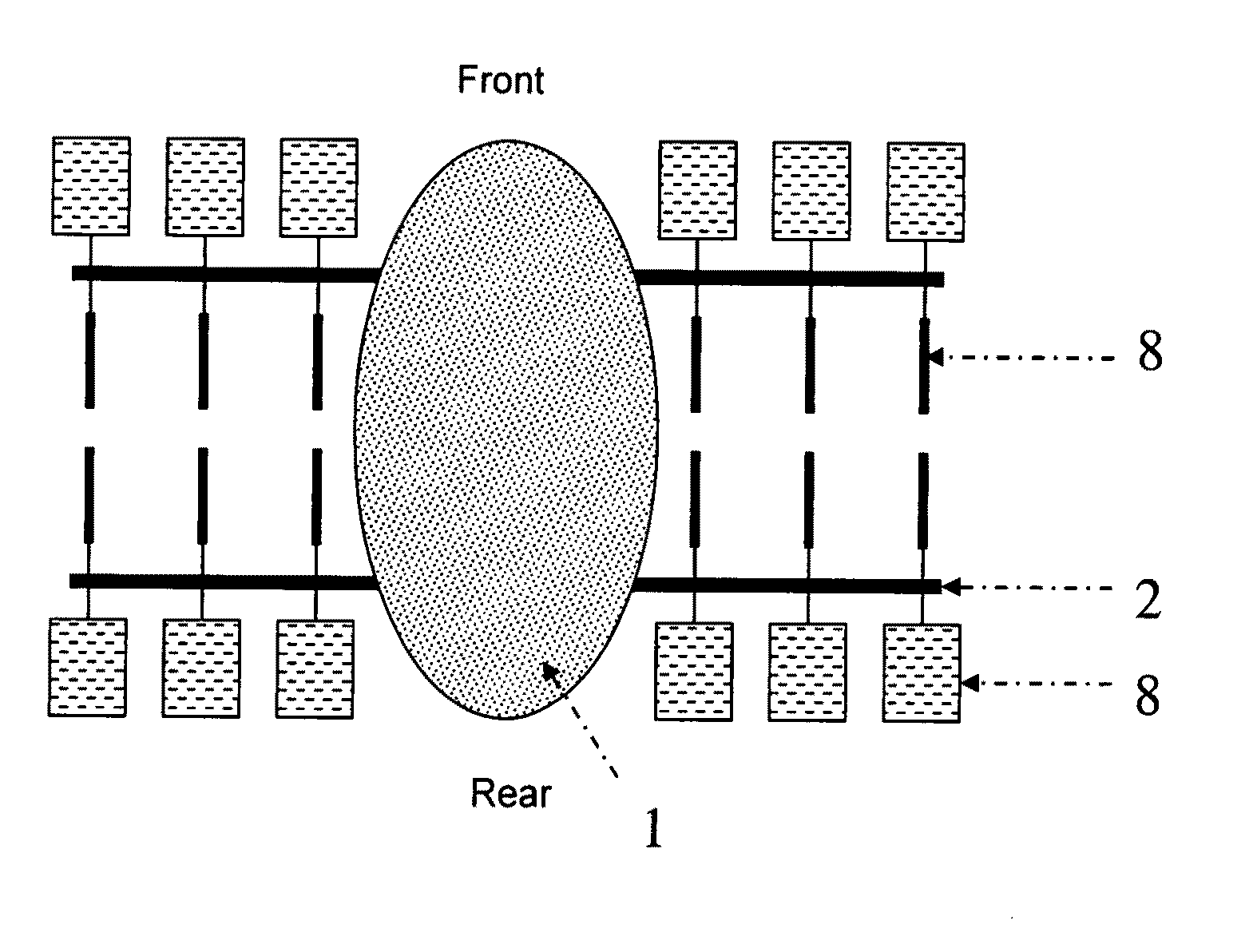
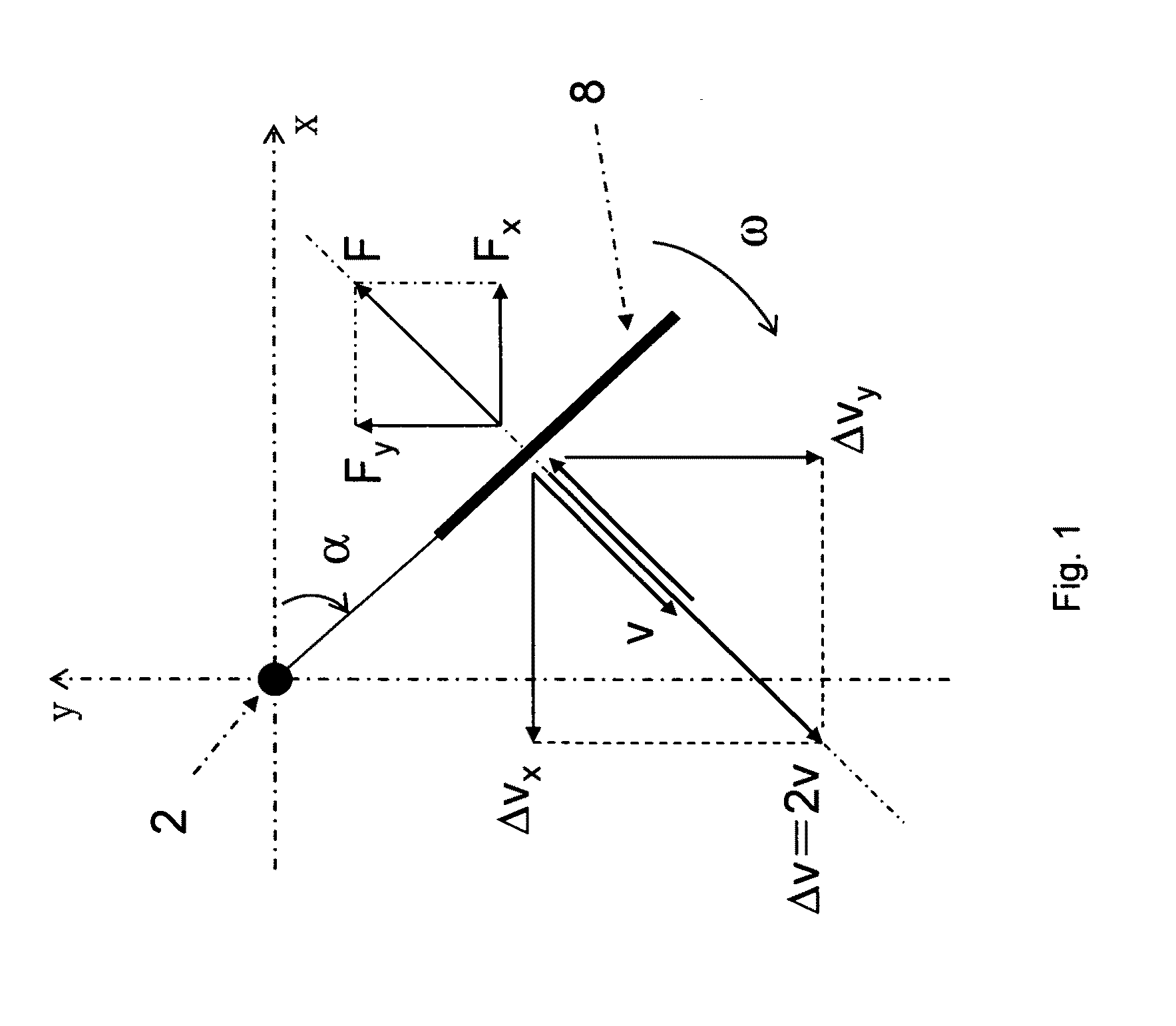
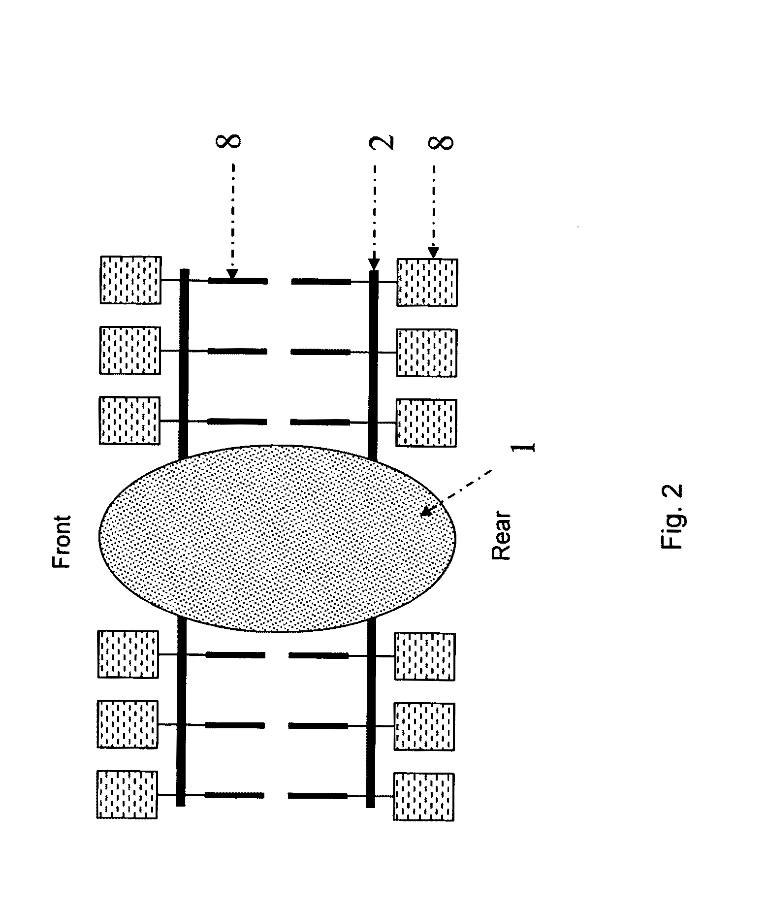
A vehicle capable of driving on land, air or water comprises of a fuselage (1), a main engine or a main motor, and a power control and transmitting system. A main shaft (2) is provided at two sides of the fuselage. Blade sleeves (6) are fixed to the main shafts. Blade handles (7) capable of spinning around own axes are mounted on the blade sleeves. Blades are fixed to the blade handles. Blade open-close devices are installed on the fuselage and / or on the main shafts to control the blades to rotate relative to the blade sleeves and the main shafts. The blade open-close device is a mechanism that can open and close the blades once a cycle of rotating along with the main shaft. When opened, blades' broad flat surfaces are parallel or generally parallel with the main shafts. When closed, the blades' broad flat surfaces are perpendicular or generally perpendicular to the main shafts. The present invention can offer lift and propulsion force through controlling the opening and closing of the blades rotating in vertical planes parallel to the fuselage.

Description

CROSS-REFERENCE TO RELATED APPLICATIONS[0001]This application claims the priority, under 35 USC §§119 of International application No. PCT / CN2009 / 074357, filed Sep. 30, 2009 with a priority date of Oct. 24, 2008 and a priority No. 200810079640.0 (CN), which designated the United State of America; this application has a prior Chinese patent No. 200820106301.2 (CN) filed on Oct. 24, 2008, and a prior Chinese patent application No. 200810079640.0 (CN) filed on Oct. 24, 2008; the prior applications are herewith incorporated by reference in their entirety.FIELD OF THE INVENTION[0002]The present invention relates to a transportation vehicle, and more particularly to a vehicle that can travel on land, in air and / or in water.BACKGROUND OF THE INVENTION[0003]There are so far mainly two kinds of aircrafts, one kind is fixed-wing aircraft and the other kind is rotary-wing aircraft. The fixed-wing aircrafts that we usually can see are passenger airplanes and cargo airplanes in airlines. Its adv...

Claims


Application Information

Patent Timeline
IPC IPC(8): B64C39/08B60F3/00
CPCB60F3/0007B64C39/00B60F5/02
Inventor LIU, GUOWENLIU, WANBING W.LIU, QUANWEN
Owner LIU GUOWEN
Learn More