Vibration generator

a generator and vibration technology, applied in the field of vibration generators, can solve problems such as the strengthening of the vibrating force, and achieve the effect of reducing the size of the vibration generator

Inactive Publication Date: 2011-08-18
SANYO SEIMITSU
View PDF7 Cites 84 Cited by
  • Summary
  • Abstract
  • Description
  • Claims
  • Application Information

AI Technical Summary

Benefits of technology

Summarizing the advantageous effects of the present invention, in the present invention, the magnetization direction of the ring-shaped permanent magnet is the axial direction parallel to the magnetic core member, and, in the first concentrated flux path by the first ring-shaped pole piece, along with alternation of the feed of current to the first toroidal coil, the electromagnetic force which is applied to the ring-shaped permanent magnet switches to forward and reverse with respect to the axial direction, so compared with the conventional drive by magnetic attraction / repulsion, drive by a high vibrating force is possible. The magnetic force lines of the outer circumference side part of the ring-shaped permanent magnet are short circuited at the thickness direction of the ring-shaped permanent magnet, so it is possible to realize a reduced size of the vibration generator without a detrimental effect on the first concentrated flux path etc.
of the present invention, in the present invention, the magnetization direction of the ring-shaped permanent magnet is the axial direction parallel to the magnetic core member, and, in the first concentrated flux path by the first ring-shaped pole piece, along with alternation of the feed of current to the first toroidal coil, the electromagnetic force which is applied to the ring-shaped permanent magnet switches to forward and reverse with respect to the axial direction, so compared with the conventional drive by magnetic attraction / repulsion, drive by a high vibrating force is possible. The magnetic force lines of the outer circumference side part of the ring-shaped permanent magnet are short circuited at the thickness direction of the ring-shaped permanent magnet, so it is possible to realize a reduced size of the vibration generator without a detrimental effect on the first concentrated flux path etc.

Problems solved by technology

This leads to strengthening of the vibrating force.

Method used


Image

  • Vibration generator
  • Vibration generator
  • Vibration generator

Examples


first embodiment

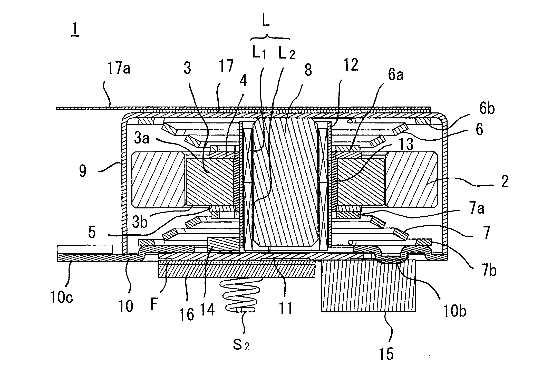
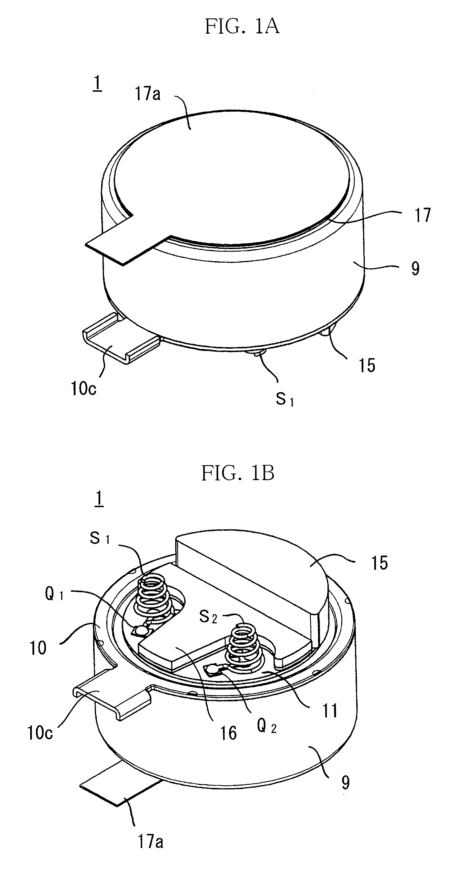
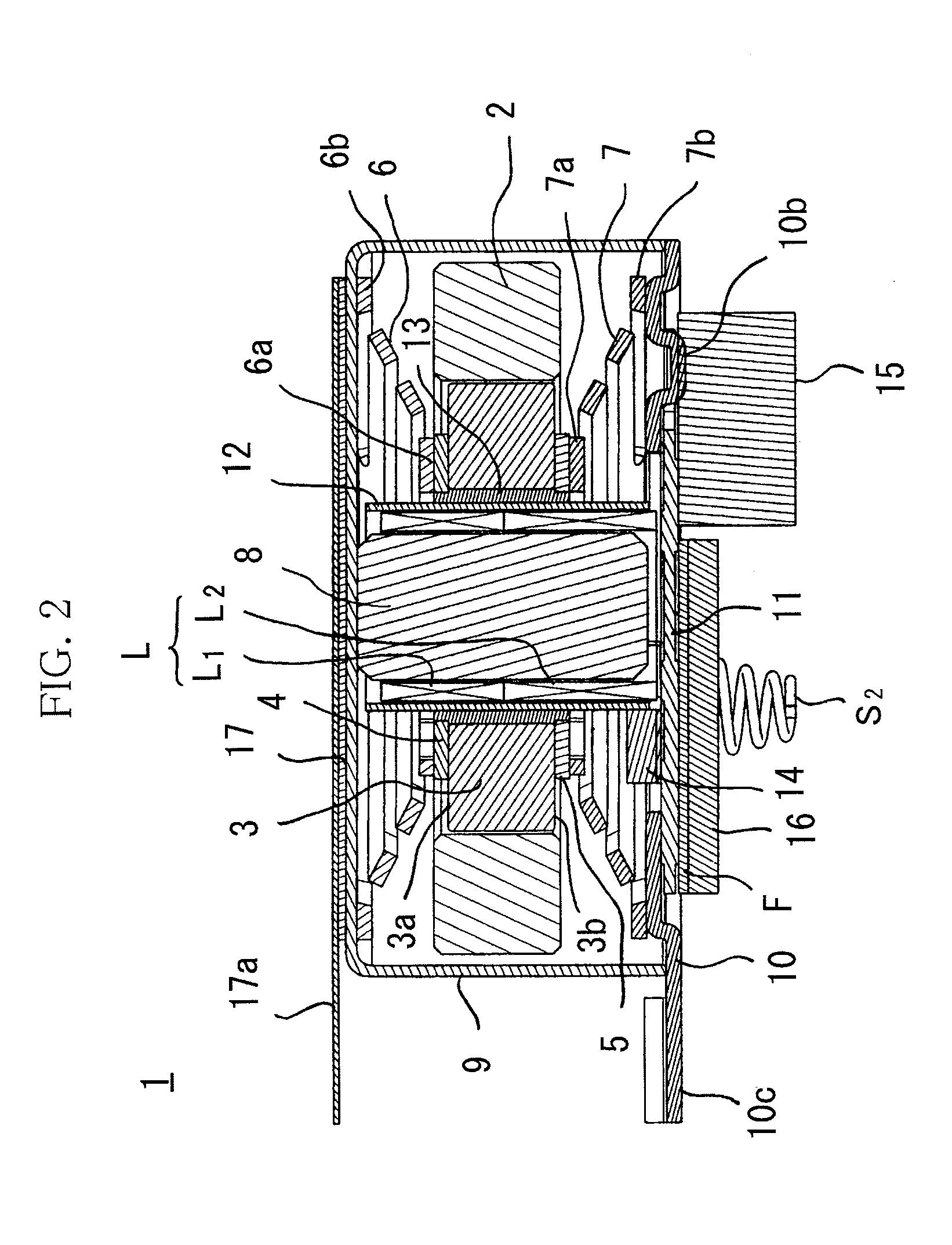
The vibration linear actuator 1 of this embodiment is provided with a ring-shaped permanent magnet 3 which is fit in a center hole H of a ring-shaped weight 2 and which is magnetized by a single pole in a thickness direction between a top end face (S pole face) 3a and bottom end face (N pole face) 3b, a ring-shaped top pole piece 4 which is adhered to the top end face 3a by an adhesive, a ring-shaped bottom pole piece 5 which is adhered to the bottom end face 3b by an adhesive, a top plate spring 6 having an inner circumference side hanging part 6a fastened to the top pole piece plate 4 by for example spot welding, adhesion, or another means and having an outer circumference side hanging part 6b fastened to a bottom surface of a recessed case 9, a bottom plate spring 7 having an inner circumference side hanging part 7a fastened to the bottom pole piece plate 5 and having an outer circumference side hanging part 7b fastened to an end plate 10 fastened to an opening side of the recess...

second embodiment

The point of difference of the vibration linear actuator of the second embodiment shown in FIGS. 9A and 9B from the vibration linear actuator of the first embodiment 1 lies in the configuration of a columnar core 18. The columnar core 18 has a center core (center iron core member) 18a which fits inside the lower toroidal coil L2 and the upper toroidal coil L1 straddling the two, a bottom permanent magnet (permanent magnet core member) 18c which has an N pole face provided in an inside the lower toroidal coil L2 and overlaid on one end face of the center core 18a, and a top permanent magnet 18b which has an S pole face provided in an inside the top toroidal coil L1 and overlaid on another end face of the center core 18a. Note that the rest of the configuration is the same as the first embodiment.

In such a configuration of the columnar core 18, even if the feed of current to the toroidal coils L1 and L2 alternates, the magnetization direction of the center core 18a is determined by th...

third embodiment

A columnar core 28 of a vibration linear actuator of the third embodiment shown in FIGS. 10A and 10B, opposite to the configuration of the columnar core 18 of the second embodiment, has a center permanent magnet 28a which fits inside the lower toroidal coil L2 and the upper toroidal coil L1 straddling the two and which has a magnetization direction of the reverse direction from the magnetization direction of the ring-shaped permanent magnet 3, a bottom core (iron core member) 28c provided in an inside the lower toroidal coil L2 and overlaps the S pole face of the center permanent magnet 28a, and a top core 28b provided in an inside the upper toroidal coil L1 and overlaps the N pole face of the center permanent magnet 28a. The magnetization directions of the bottom core 28c and top core 28b match the magnetization direction of the center permanent magnet 28a, so the magnetic force lines which run from the bottom pole piece 5 through the lower toroidal coil L2 to enter the columnar co...


PUM


Abstract

A vibration generator making a closed loop of a magnetic circuit of a permanent magnet to obtain a high vibrating force while kept small in size, including a reciprocating vibrator having a ring-shaped permanent magnet in a center hole of a ring-shaped weight, a first and second plate springs supporting this reciprocating vibrator at a recessed case and end plate to be able to elastically displace in a thickness direction spanning a first and a second end faces, a tubular toroidal coil passing through a center hole of the permanent magnet and generating a reciprocating vibrating magnetic field for reciprocatingly driving the permanent magnet in the thickness direction, and a columnar core passing through this toroidal coil, the ring-shaped permanent magnet being magnetized in the thickness direction, and the toroidal coil having a lower toroidal coil and an adjoining reversely wound series connected upper toroidal coil coaxial with the same.

Description

CROSS-REFERENCE TO RELATED APPLICATIONThis application is based upon and claims the benefit of priority of the prior Japanese Patent Application No. 2010, 031208, filed on Feb. 16, 2010, and the prior Japanese Patent Application No. 2011, 006513, filed on Jan. 15, 2011, the entire contents of which are incorporated herein by reference.BACKGROUND OF THE INVENTION1. Field of the InventionThe present invention relates to a vibration generator which is built into a mobile phone etc., more particularly relates to the structure of a vibration generator by which a high vibrating force is obtained.2. Description of the Related ArtAs shown in FIG. 17, the vibration linear actuator 51 disclosed in Japanese Patent Publication (A) No. 2003-154314 is provided with a ring-shaped external yoke 54 as a weight having a cylindrical permanent magnet 55 at its inner circumference side, a first plate spring 57 fastened to a first end face 54a of this external yoke 54 by elastically deforming an outer ci...

Claims


Application Information

Patent Timeline
Patent Type & Authority Applications(United States)
IPC IPC(8): H02K35/06
CPCH02K41/0356H02K33/16
Inventor FURUICH, KEISUKEMIYAZAKI, MASAHIKOAKANUMA, TOMOHIROTAKAGI, TAKAHIRO
Owner SANYO SEIMITSU
Why Eureka
Try Eureka