Light-emitting diode driving apparatus and light-emitting diode lighting controlling method

a technology of light-emitting diodes and driving apparatus, which is applied in the direction of instruments, light sources, electroluminescent light sources, etc., can solve the problems of short life of electrolytic capacitors, large coils used in switching power supply, and excessive current flowing through leds, so as to improve the operation efficiency and power factor of leds, smooth out deviation, and improve the effect of power factor

Active Publication Date: 2011-08-18
NICHIA CORP
View PDF4 Cites 139 Cited by
  • Summary
  • Abstract
  • Description
  • Claims
  • Application Information

AI Technical Summary

Benefits of technology

[0017]The present invention is devised to solve the above problems. It is a main object to provide a light-emitting diode driving apparatus and a light-emitting diode driving operation controlling method capable of improving the operation effici...

Problems solved by technology

Conversely, a voltage applied to the LEDs exceeds Vf, an excessive amount of current will flow through the LEDs.
Also, generally, the life of electrolytic capacitors will be short, in the case where the ambient temperature is high.
A coil used in the switching power supply also will be large and deteriorate under high temperature condition.
Since the switching power supply circuit switches very quickly between full-on and full-off states at a large amount of current, noise is likely to be generated.
However, as shown by shaded areas in the voltage waveform in FIG. 11, most of electric power will be consumed to generate heat, and as a result is not used for light emission.
Accordingly, power supply efficiency will greatly decrease.
As discussed above, if the Vf total value is adjusted small to increase the LED operation efficiency, power will be wasted to generate heat.
These requirements are contradictory to each other.
However, in this method, since the microcomputer is used to select connect the LED block based on the result of a detected voltage value of input waveform, complicated control is available but the circuit configuration becomes expensive.
For this reason, this method is not suitable for inexpensive lighting apparatu...

Method used


Image

  • Light-emitting diode driving apparatus and light-emitting diode lighting controlling method
  • Light-emitting diode driving apparatus and light-emitting diode lighting controlling method
  • Light-emitting diode driving apparatus and light-emitting diode lighting controlling method

Examples


example 1

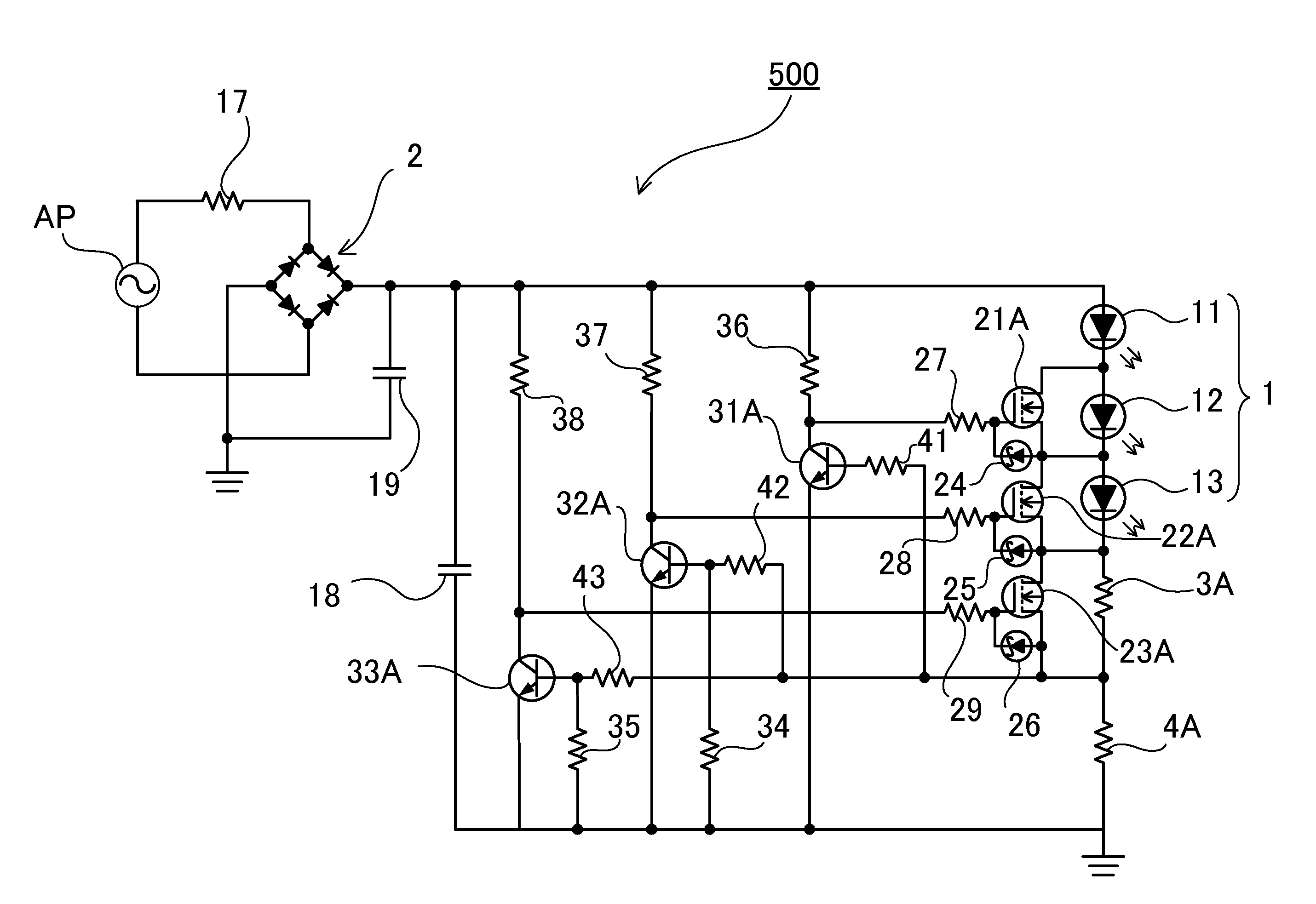
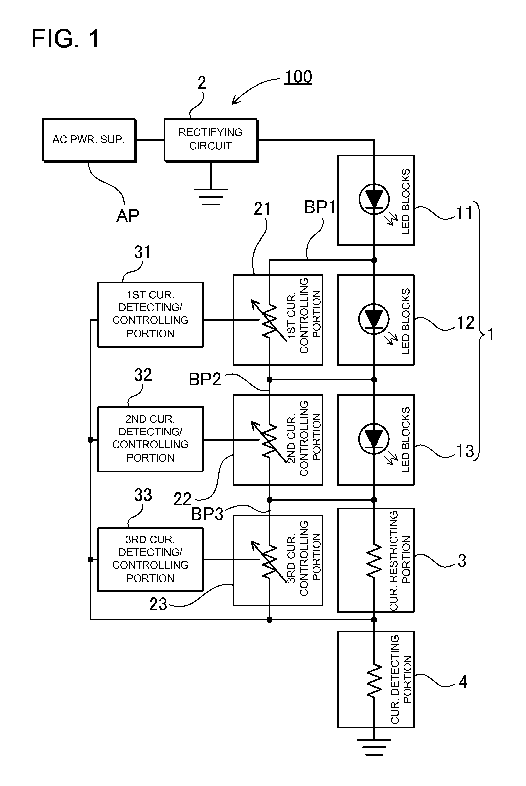
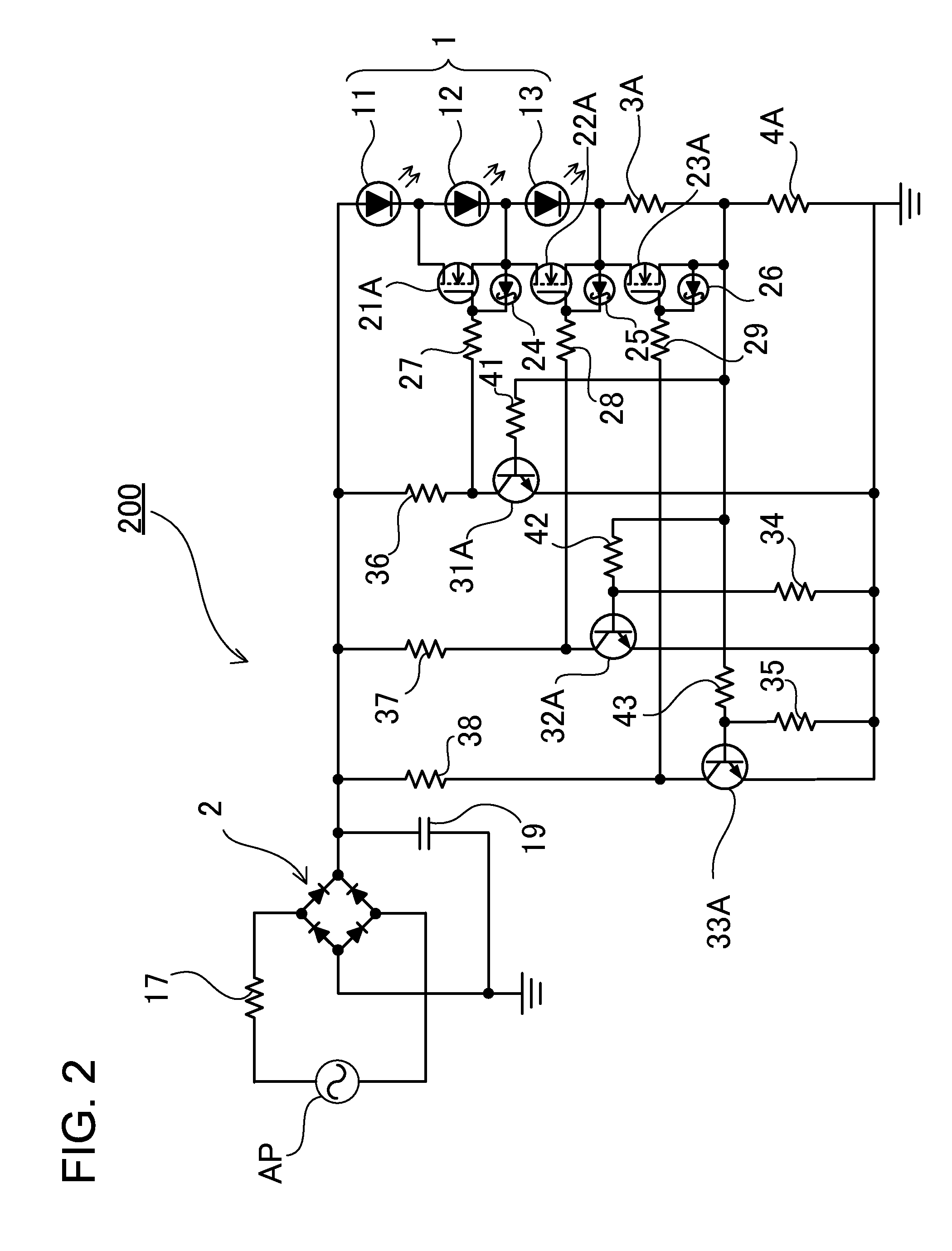
[0062]FIG. 2 shows an exemplary circuit according to an example 1 that is composed of semiconductor elements to realize the configuration shown in FIG. 1. In a light-emitting diode driving apparatus 200 shown in this Figure, a diode bridge is used as the rectifying circuit 2 connected to the AC power supply AP. A protection resistor 17 is connected between the AC power supply AP and the rectifying circuit 2. A bypass capacitor 19 is connected to the output side of the rectifying circuit 2.

(AC Power Supply AP)

[0063]The 100-V commercial power can be suitably used as the AC power supply AP. The voltage 100 V in this commercial power is an effective value. The maximum voltage of a rectified waveform subjected to full-wave rectification will be about 141 V.

(Led Block)

[0064]A plurality of LEDs are divided into a plurality of LED blocks. The LED blocks are connected to each other in series. Terminals are provided between the blocks, and are connected to the current controlling portions. Th...

example 2

[0093]In the foregoing example, operation is controlled in consideration of power factor. In particular, since the LED blocks of LED block group 1 are connected to each other in series by one line in the exemplary circuit shown in FIG. 2, in the case where the LED blocks are driven at different current values, a current wave form has a stepped shape as shown in the graph of FIG. 3. In contrast to this, FIG. 4 shows an exemplary voltage waveform according to example 2 in that greater importance is placed on operation efficiency rather than power factor. According to exemplary control of this example, constant current values for LED blocks are specified closer to each other than the exemplary control of the example shown in FIG. 3 by specifying the resistances of the resistors and the like. Accordingly, the entire current amount is increased to increase the output of the LED driving apparatus. Therefore, it is possible to provide bright lighting. In the case where circuit parameters a...

example 3

[0094]In the foregoing examples, the LED current detecting resistor is a common resistor to the LED blocks, and the like. That is, since the current detecting / controlling portions control LED light emission based on the amount of a current of the common current detecting portion, the circuit configuration can be simple. However, LED current detecting resistors can be provided block by block, and the like. This type of circuit is shown as an example 3 in a circuit diagram of FIG. 5. A light-emitting diode driving apparatus 300 shown in this Figure has a basic configuration similar to the example 1, and operate similarly to the example 1. However, the light-emitting diode driving apparatus 300 includes LED current detecting resistors that are provided for the three LED blocks. Specifically, first, second and third LED current detection resistors 4B, 4C and 4D detect currents in the second LED block 12, the third LED block 13 and an LED current restriction resistor 3B, respectively. In...


PUM


Abstract

A LED driving apparatus includes a rectifying circuit 2, first, second and third blocks 11, 12 and 13, and first and second switching portions. The rectifying circuit 2 is connected to AC power supply, and rectifies AC voltage of the AC power supply to provide pulsating current voltage. Each block includes a plurality of LEDs. The first, second and third blocks 11, 12 and 13 are serially connected to the output side of the rectifying circuit 2. The first switching portion switches ON/OFF of a first bypass path BP1 based on flowing current amount in the first block 11. The first bypass path BP1 bypasses the second block 12. The second switching portion switches ON/OFF of a second bypass path BP2 based on flowing current amount in the first and second blocks 11 and 12. The second bypass path BP2 bypasses the third block 13.

Description

BACKGROUND OF THE INVENTION[0001]1. Field of the Invention[0002]The present invention relates to a light-emitting diode driving apparatus and a light-emitting diode driving operation controlling method, and in particular to a light-emitting diode driving apparatus and a light-emitting diode driving operation controlling method using AC power supply.[0003]2. Description of the Related Art[0004]In recent years, significant attention is given to light-emitting diodes (hereinafter, occasionally referred to as “LEDs”) as lighting sources. The reason is that LEDs can be driven at low power consumption as compared with filament lamps or fluorescent lamps. LEDs are small, and have shock resistance. In addition, LEDs are less prone to burn out. Thus, LEDs have these advantages.[0005]In the case of lighting sources, it is desirable that AC power such as commercial power for home use is used as power supply for lighting sources. LEDs are devices driven by DC power. LEDs emit light only when ap...

Claims


Application Information

Patent Timeline
IPC IPC(8): H05B37/02
CPCH05B33/083H05B33/0824H05B45/44H05B45/48
Inventor MUGURUMA, SHUJIOGURA, WATARUWATANABE, TERUO
Owner NICHIA CORP
Why Eureka
Try Eureka