Secondary battery power control method

a secondary battery and power control technology, applied in secondary cell servicing/maintenance, electrochemical generators, greenhouse gas reduction, etc., can solve the problems of difficult to stably supply power from the interconnected system to the power system for a long time, and achieve the effect of suppressing secondary battery deterioration, stably providing power to the power system for a long time, and efficient operation

Active Publication Date: 2011-08-18
NGK INSULATORS LTD
View PDF9 Cites 17 Cited by
  • Summary
  • Abstract
  • Description
  • Claims
  • Application Information

AI Technical Summary

Benefits of technology

[0012]The present invention was conceived in view of the above problems. An object of the present invention is to provide a secondary battery power control method for efficiently operating an interconnected system that can stably supply power to a power system for a long time by suppressing a deterioration in the secondary battery.
[0016]According to the method of controlling power discharged from a secondary battery of the present invention, the maximum discharge power of the secondary battery is limited using the bidirectional converter when the temperature of the secondary battery detected by the temperature detection section has exceeded a preset temperature. Therefore, the secondary battery is not continuously operated to a maximum extent at a high temperature. This makes it possible to stably supply power to a power system for a long time by suppressing a deterioration in the secondary battery. Moreover, since a situation in which it is necessary to compulsory stop discharging the secondary battery rarely occurs, power can be supplied to the power system while efficiently operating the interconnected system according to the method of controlling power discharged from a secondary battery.

Problems solved by technology

This may make it difficult to stably supply power from the interconnected system to the power system for a long time.

Method used


Image

  • Secondary battery power control method
  • Secondary battery power control method
  • Secondary battery power control method

Examples


Embodiment Construction

[0022]Exemplary embodiments of the present invention are described below. Note that the present invention is not limited to the following embodiments. Various modifications and improvements may be appropriately made of the following embodiments based on the common knowledge of a person having ordinary skill in the art without departing from the scope of the present invention.

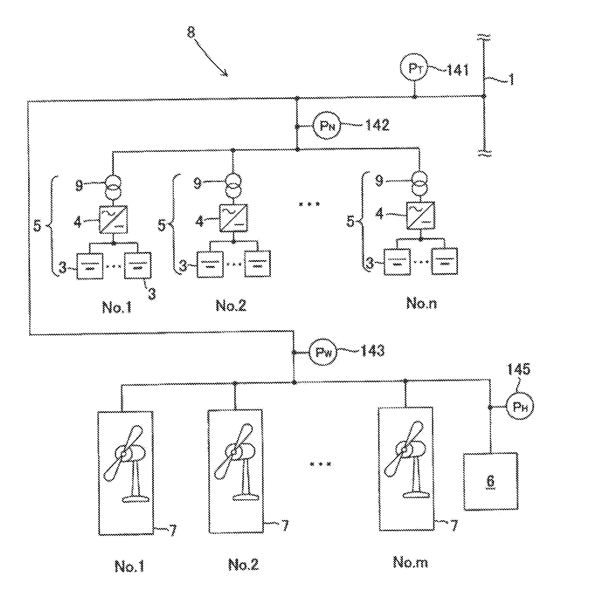
[0023]A secondary battery power control method according to the present invention controls power discharged from a secondary battery included in an interconnected system that supplies power to a power system, the interconnected system including a power generator that changes in output power, and an electric power storage-compensation device that includes a secondary battery, and compensates for a change in output power of the power generator. The term “secondary battery” used herein refers to a secondary battery that is defined in a secondary battery section divided by control sections. The number of single cell...


PUM

PropertyMeasurementUnit
temperatureaaaaaaaaaa

Abstract

A secondary battery power control method controls power discharged from a secondary battery included in an interconnected system that supplies power to a power system, the interconnected system including a power generator that changes in output power, and an electric power storage-compensation device that includes a secondary battery, and a bidirectional converter that controls charging / discharging of the secondary battery, and compensates for a change in output power of the power generator. A temperature detection section that detects the temperature of the secondary battery is annexed to the secondary battery, and the maximum discharge power of the secondary battery is limited using the bidirectional converter when the temperature of the secondary battery detected by the temperature detection section has exceeded a preset temperature.

Description

TECHNICAL FIELD[0001]The present invention relates to a secondary battery power control method for an interconnected system that supplies power to a power system, and includes a power generator (e.g., wind power generator) that changes in output power, and an electric power storage-compensation device that includes a sodium-sulfur battery.BACKGROUND ART[0002]In recent years, a natural-energy power generator that generates power by utilizing wind power, solar power, geothermal energy, or the like has attracted attention, and has been put to practical use. A natural-energy power generator is a clean power generator that utilizes an inexhaustible natural energy source instead of limited resources (e.g., petroleum), and can suppress carbon dioxide emissions. Therefore, various companies, autonomous bodies, and the like have increasingly employed a natural-energy power generator.[0003]However, since the amount of natural energy obtained varies from hour to hour, a natural-energy power ge...

Claims


Application Information

Patent Timeline
Patent Type & Authority Applications(United States)
IPC IPC(8): H01M10/46H02J7/00
CPCH01M10/3909H01M10/443H01M10/486Y02E10/763H02J3/386Y02E70/30H02J3/32H02J2300/28H02J3/381Y02E10/76Y02E60/10H02J7/007194
Inventor ABE
Owner NGK INSULATORS LTD
Why Eureka
Try Eureka