
Power transfer device and method

a power transfer device and power technology, applied in the direction of transformers, inductances, transportation and packaging, etc., can solve the problems of interference with signal transmission and reception in the antenna and other directions

Inactive Publication Date: 2011-08-18
CONVENIENTPOWER HK
View PDF32 Cites 63 Cited by
  • Summary
  • Abstract
  • Description
  • Claims
  • Application Information

AI Technical Summary

Benefits of technology

"The present invention provides a power transfer device that can wirelessly transfer AC power to charge a load. The device has a phase-shift control means to control the wireless transfer of the AC power. The device includes a power converter for generating the AC power, and the phase-shift control means controls the power converter. The device uses a spread-spectrum technique to transfer the AC power at a specific frequency. The technical effect of this invention is to enable efficient and safe wireless transfer of AC power for charging loads."

Problems solved by technology

However, unlike the design objectives of switched mode power supplies which focus mainly on energy efficiency and voltage regulation, power converters for wireless charging systems have to cope with not only the dynamic wireless power transfer, voltage regulation and efficiency requirements but also, and more importantly, the radio-frequency (RF) aspects of the systems.
The AC electromagnetic flux generated by the power converter of a wireless charging system can cause interference with the signal transmission and reception in the antenna and other sub-systems of the electronic load being charged since energy is transferred through the AC magnetic flux to the load (the Applicant's previous U.S. patent application Ser. No. 12 / 566,438 titled “Antenna Network for Passive and Active Signal Enhancement” addressed other problems related to similar issues that are encountered in these wireless power transfer applications).

Method used


Image

  • Power transfer device and method
  • Power transfer device and method
  • Power transfer device and method

Examples


Embodiment Construction

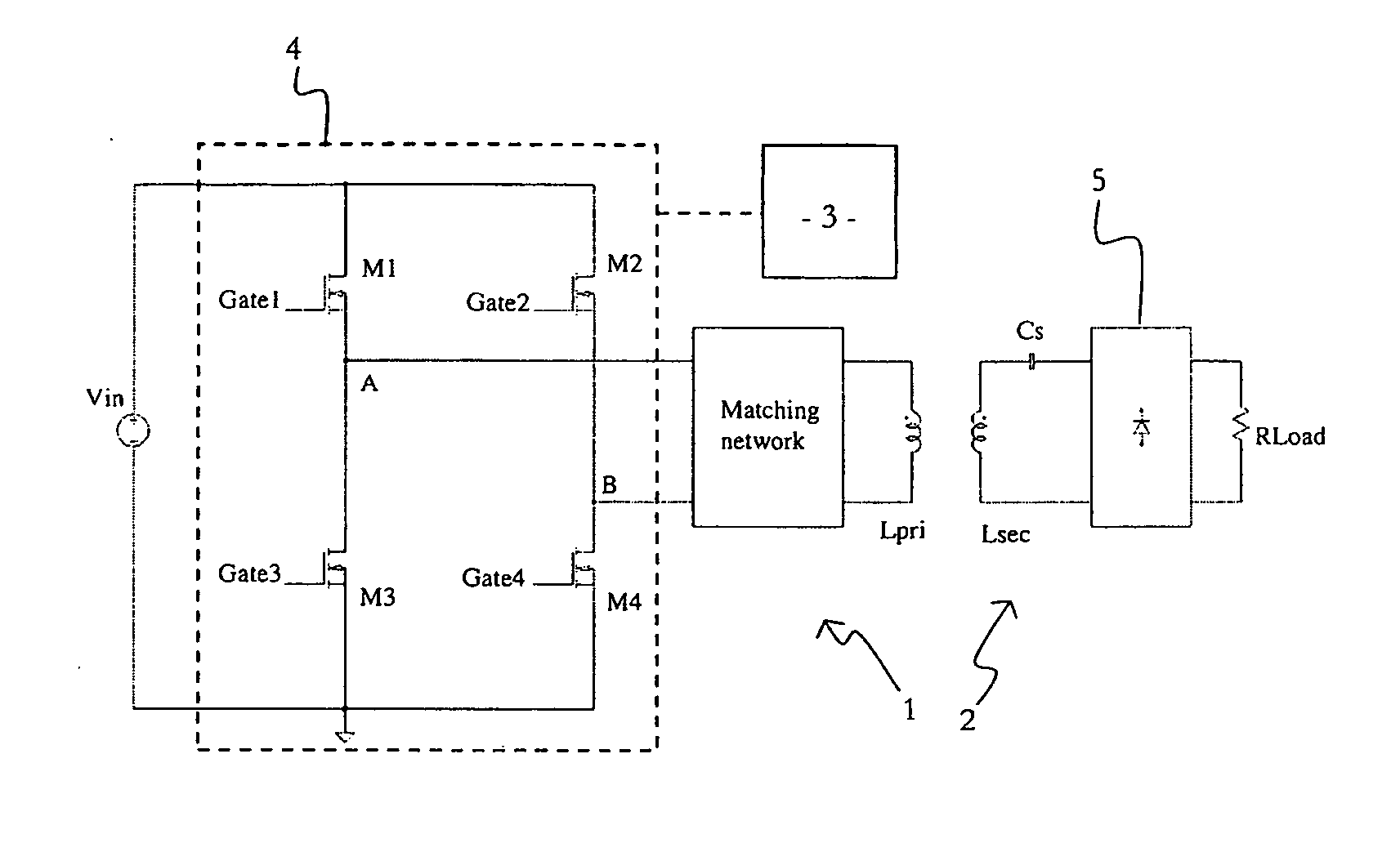
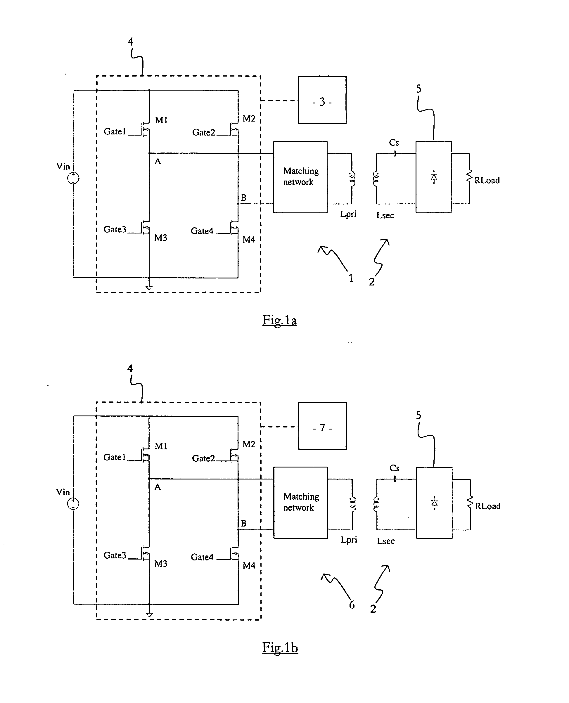
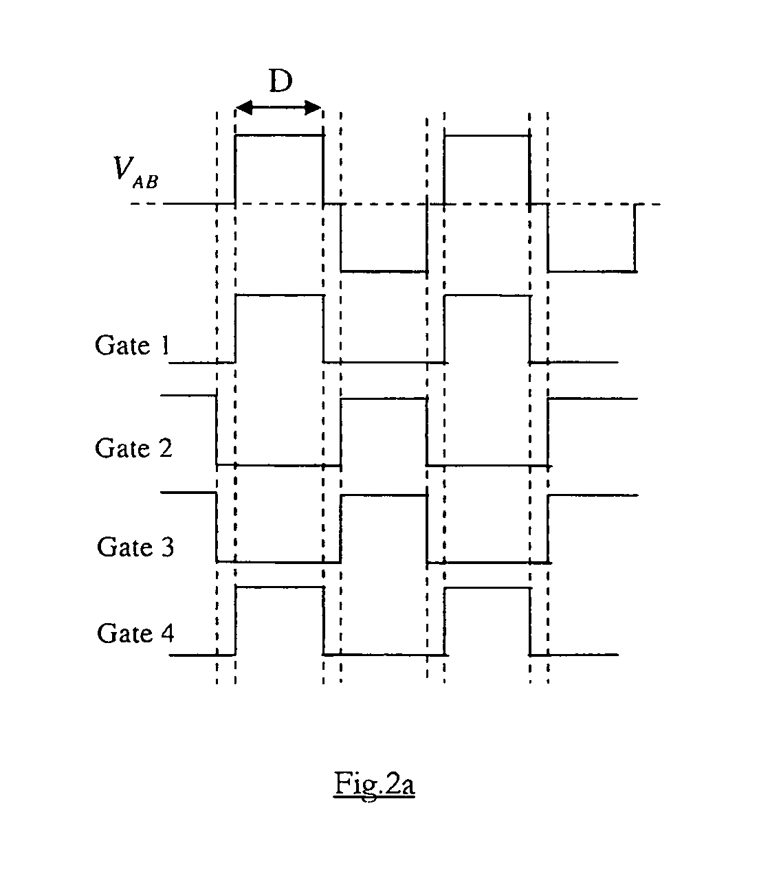
Referring to the figures, there is provided a power transfer device 1 that wirelessly transfers AC power for charging at least one load 2, the power transfer device having a phase-shift control means 3 to control the wireless transfer of the AC power.

The power transfer device 1 includes a power converter 4 for generating the AC power, and the phase-shift control means 3 controls the power converter. In the present embodiment, the power converter 4 is a DC-AC power converter, which is also known as an inverter.

The power transfer device 1 includes a primary winding Lpri for inductively transferring the AC power to a secondary winding Lsec, thereby wirelessly transferring the AC power. The secondary winding Lsec includes a series capacitor C, for reducing any leakage inductance. The secondary winding Lsec is also connected to a rectifier 5, which is preferably a synchronous rectifier.

The secondary winding Lsec, forms part of the load 2. Preferably, the power transfer device 1 wirelessl...


PUM


Abstract

The present invention provides a power transfer device that wirelessly transfers AC power for charging at least one load, and an associated method of wirelessly transferring power. The device and method of the invention use phase-shift control to control the wireless transfer of the AC power.

Description

FIELD OF THE INVENTIONThe present invention relates to power transfer devices, particularly power transfer devices for wirelessly charging loads. The invention will be described in the context of power transfer devices that wirelessly charge the batteries of portable wireless communication devices. However, it will be appreciated that the invention is not limited to this particular use.BACKGROUND OF THE INVENTIONTraditional battery chargers transfer power to the batteries through electrical wires. Many switching control methods such as duty-cycle control, frequency control and phase-shift converter have been proposed for voltage regulation and soft-switching techniques to reduce the switching losses and radiated electromagnetic interference, in order to increase the energy efficiency and comply with electromagnetic compatibility requirements, respectively. Due to the small amount of radiated electromagnetic field involved (because the power transfer is carried out through wires), tr...

Claims


Application Information

Patent Timeline
Patent Type & Authority Applications(United States)
IPC IPC(8): H02J7/00
CPCH02J5/005H02J7/025H02M2007/53878H02M3/3376H02M7/53871H02J17/00H02J50/12H02J7/00712H02M7/53878H02J50/20
Inventor HUI, SHU YUEN RONHO, WING CHOI
Owner CONVENIENTPOWER HK
Learn More