Method for operating remotely controlled cameras in an industrial process

a technology of remote control and industrial process, applied in the field of system and method for engineering and operation of video monitoring system, can solve the problems of large amount of manual engineering, cumbersome and laborious methods of controlling each cctv camera, and difficulty for operators to operate cctv camera, so as to reduce the time necessary, capture images efficiently, and capture images. the effect of a process or process obj

a technology of remote control and industrial process, applied in the field of system and method for engineering and operation of video monitoring system, can solve the problems of large amount of manual engineering, cumbersome and laborious methods of controlling each cctv camera, and difficulty for operators to operate cctv camera, so as to reduce the time necessary, capture images efficiently, and capture images. the effect of a process or process obj

US20110199487A1Inactive Publication Date: 2011-08-18ABB RES LTD

Image

  • Method for operating remotely controlled cameras in an industrial process
  • Method for operating remotely controlled cameras in an industrial process
  • Method for operating remotely controlled cameras in an industrial process

Examples


Embodiment Construction

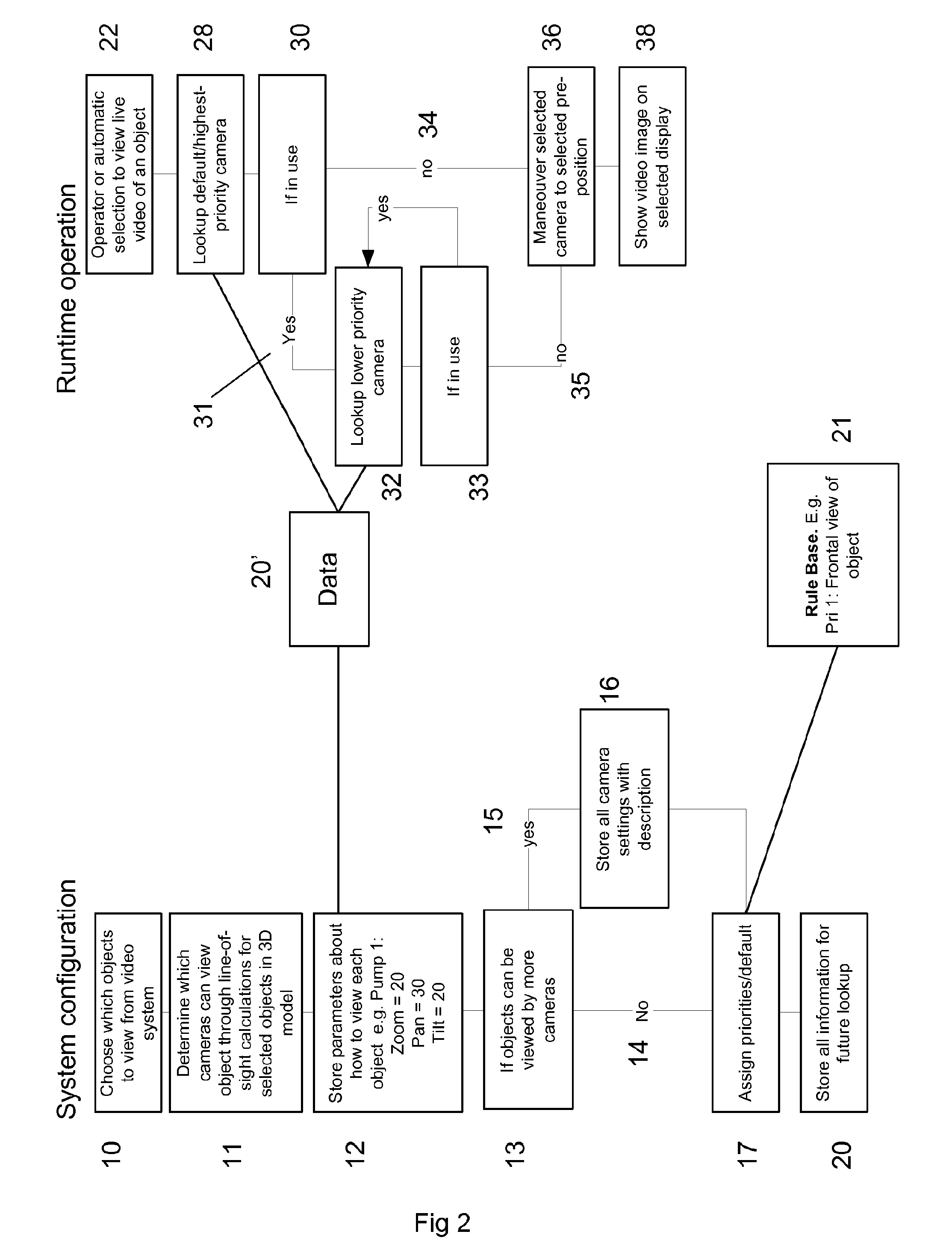
[0033]This invention describes a method that has information available about which camera should be used to view an object and further, information to be able to calculate whether a given camera has a clear line of sight to that specific object. The method also determines the settings such as pan, tilt, zoom and focus for the camera. In case there are more cameras that can view an object, the most appropriate camera is selected.

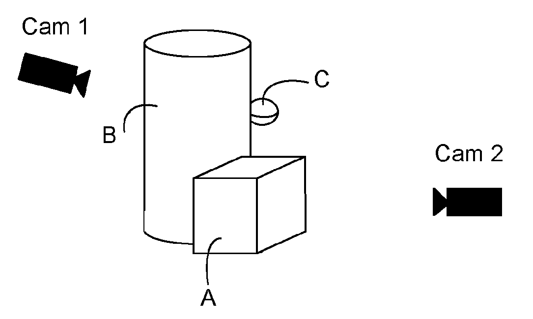
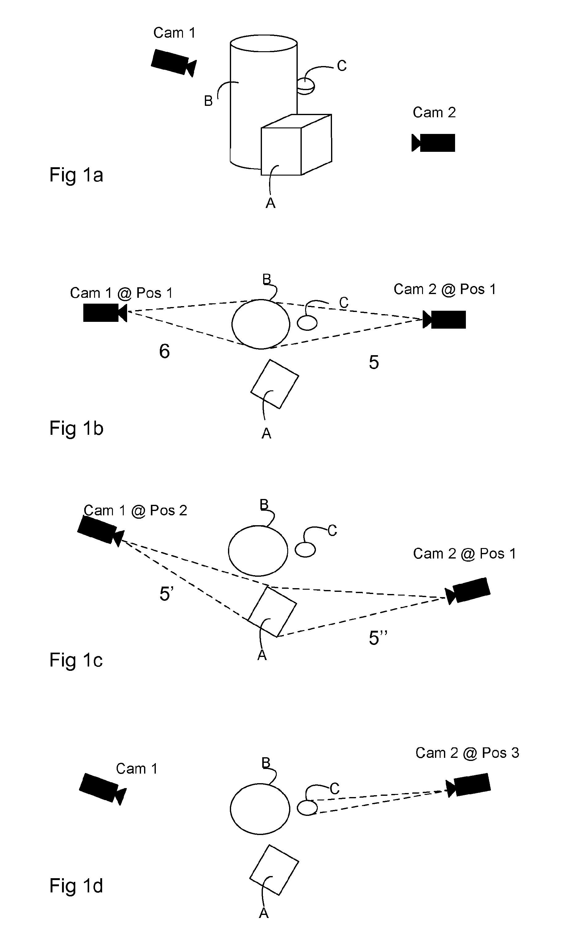
[0034]FIG. 1 a shows a 3-D view of a group of objects A, B, or C representing equipment such as a tank or a building in an industrial installation, and two cameras 1, 2 positioned nearby. Object C represents an object of interest, which may be an item of equipment, a valve, a transformer and so on. FIG. 1b shows a first view from above looking down on the objects. It is shown there that camera 1 in position 1 does not 6 have line of sight to object C, and that camera 2 at position 1 has line of sight 5 to object C. This may be calculated by a computer impleme...


PUM


Abstract

A method to operate a camera to focus on a selected object or a process object of interest in an industrial installation, and automatically calculating which camera or cameras are in line of sight of the object of interest utilizing measurements on a 3D model of the installation and the cameras. A system is also described. The camera may be automatically operated to move, or pan or tilt or zoom the camera so as to point and focus on the process object of interest. A video stream or an image of the object of interest is then generated and displayed.

Description

TECHNICAL FIELD[0001]This invention describes a system and a method for engineering and operation of a video monitoring system from within an industrial control system. In particular the invention is concerned with calculating which cameras have an unobstructed line of sight to specific locations within the process plant by means of an accurate 3D model of the plant including all onsite equipment and the location of each camera or video surveillance camera.TECHNICAL BACKGROUND[0002]In the field of process control in industrial plants there is a continual requirement for information about process equipment and process objects. As well as process monitoring equipment, temperature sensors, pressure sensors and so on, video imaging may be used to provide a real-time image of an object or a process. Display screens showing CCTV images (closed circuit television) may be arranged in a control room monitoring one or more parts of an industrial plant. CCTV images may be displayed showing par...

Claims


Application Information

Patent Timeline
18 Aug 2011
Publication
US20110199487A1
IPC
H04N7/18
CPC
G05B19/418; H04N7/181; H04N5/23203; H04N23/66
Inventors
HUSOY, KRISTOFFER; SKOURUP, CHARLOTTE