Burner arrangement

a burner arrangement and gas turbine technology, applied in the direction of machines/engines, combustion types, lighting and heating apparatus, etc., can solve the problems of high cost, achieve the effect of ensuring leakage resistance against air passage, high natural frequency, and rapid attenuation

Inactive Publication Date: 2011-08-25
SIEMENS AG
View PDF13 Cites 7 Cited by
  • Summary
  • Abstract
  • Description
  • Claims
  • Application Information

AI Technical Summary

Benefits of technology

As a result of the fit and the additional seal, in particular the sealing ring, leakproofness against the passage of air is ensured.
Preferably the support-side contact surface of the fuel nozzle has at least one opening for an attachment of the support-side contact surface to the supporting surface of the support. In a preferred embodiment the opening is a bored hole and the attachment is a screw connection or a bolt connection. Preferably six bored holes are provided in the support-side contact surface for screw or bolt connections, the bored h

Problems solved by technology

These are howeve

Method used


Image

  • Burner arrangement
  • Burner arrangement
  • Burner arrangement

Examples


Embodiment Construction

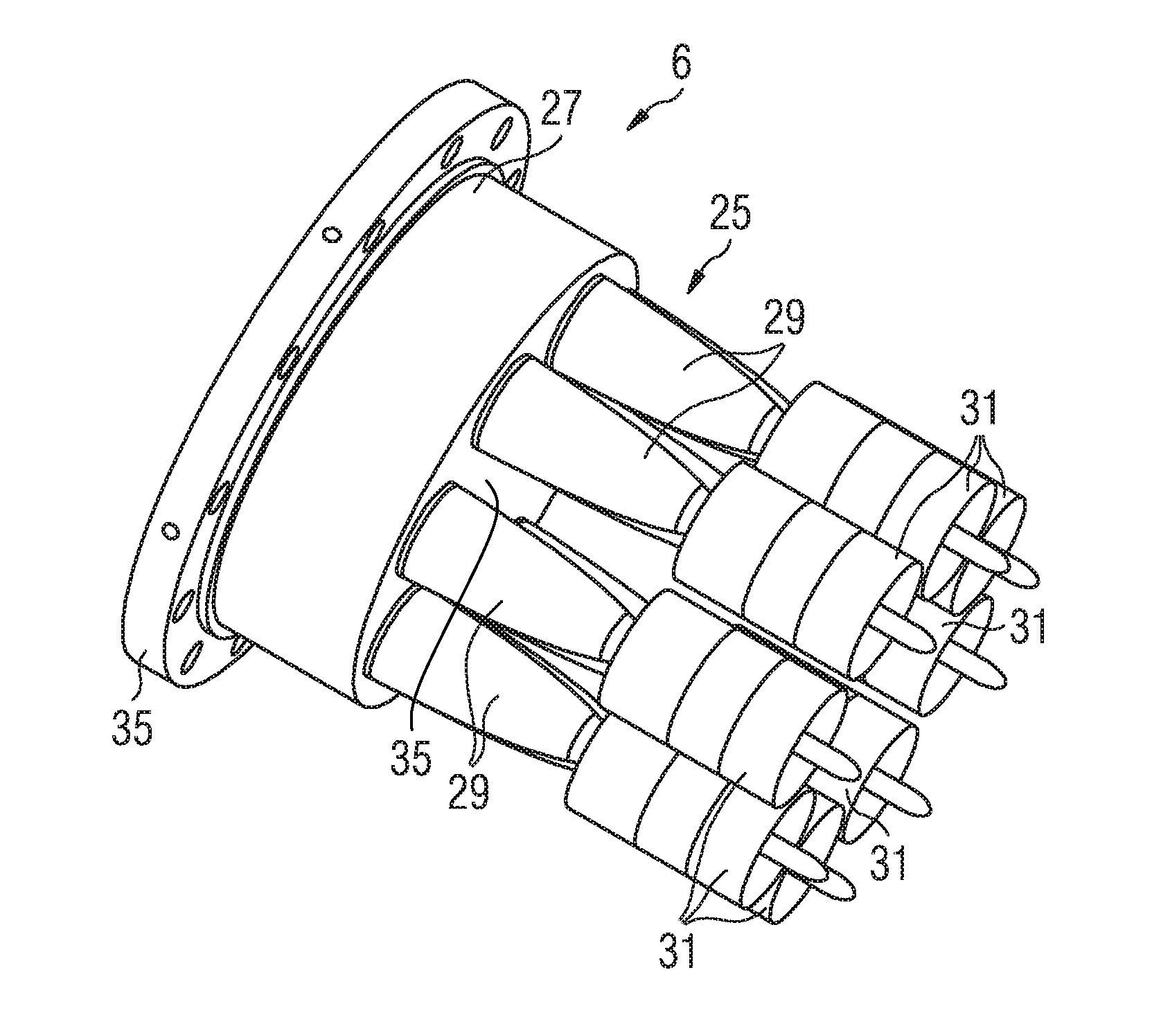
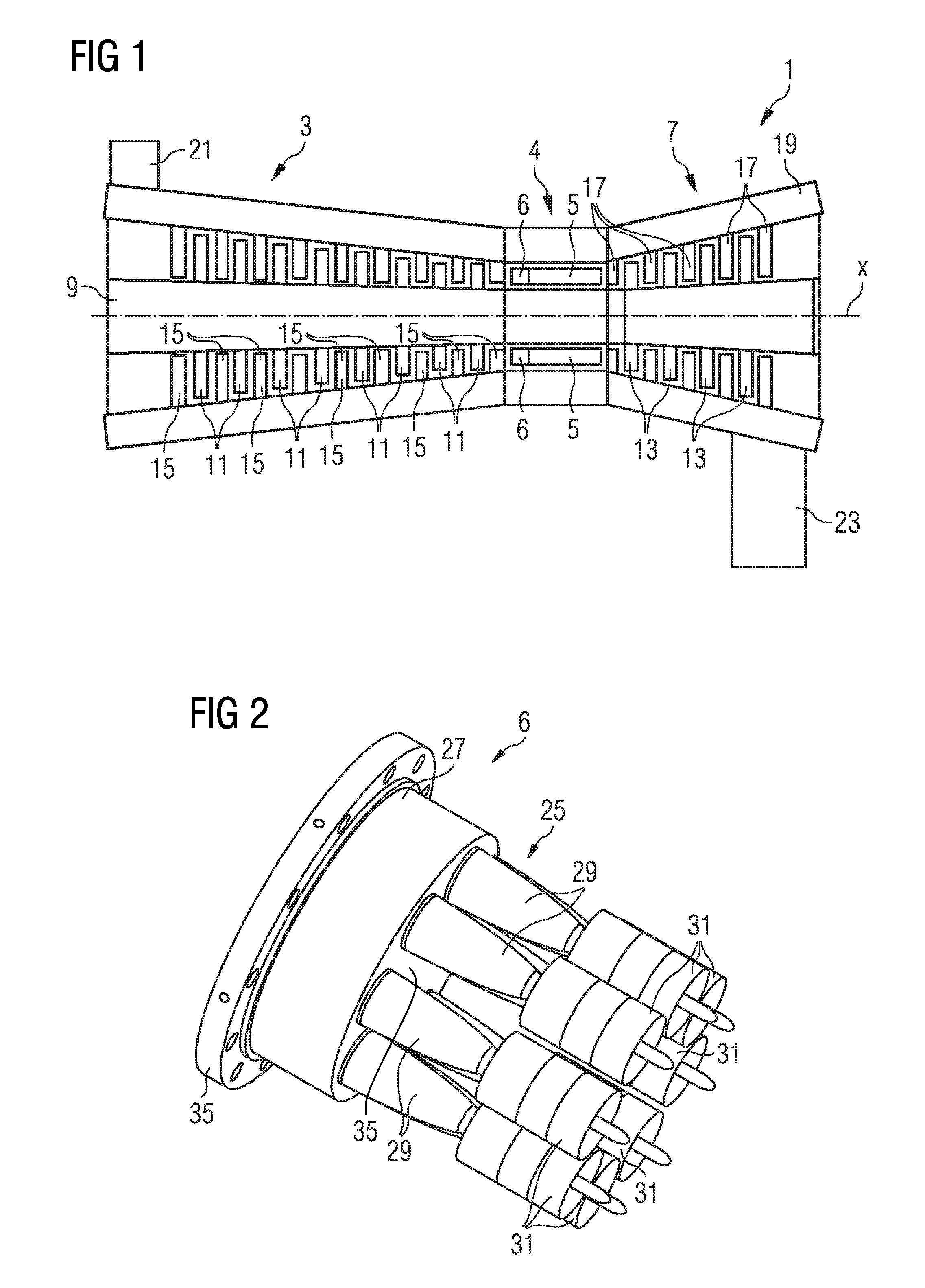
The structure and function of a gas turbine are explained below on the basis of FIG. 1, which shows a highly diagrammatic sectional view of a gas turbine. The gas turbine 1 includes a compressor section 3, a combustion section 4 which in the present exemplary embodiment includes a plurality of pipe combustion chambers 5 with burners 6 arranged thereon, but which can fundamentally also include an annular combustion chamber, and a turbine section 7. A rotor 9 extends through all sections and in the compressor section 3 supports compressor blade rings 11 and in the turbine section 7 turbine blade rings 13. Rings composed of compressor guide vanes 15 or rings composed of turbine guide vanes 17 are arranged between adjacent compressor blade rings 11 and between adjacent turbine blade rings 13, said rings extending out radially from a housing 19 of the gas turbine 1 in the direction of the rotor 9.

During operation of the gas turbine 1 air is sucked in through an air inlet 21 into the comp...


PUM


Abstract

A burner arrangement is provided. The burner arrangement includes a support as well as at least two fuel nozzles, with fuel nozzle tips, attached to the support in the direction of flow and a gas feed system to the fuel nozzle tips extending through the support. Each fuel nozzle includes a support-side section which on the support side includes a contact surface with which the fuel nozzle rests on a supporting surface of the support, at least two fuel nozzle tips formed in one piece running from the support-side section in the direction of flow, the gas feed system including at least one gas feed line and its lead-through through the support, the lead-through being embodied as a fit.

Description

CROSS REFERENCE TO RELATED APPLICATIONSThis application claims priority of European Patent Office application No. 10154109.2 EP filed Feb. 19, 2010, which is incorporated by reference herein in its entirety.FIELD OF INVENTIONThe present invention relates to a burner arrangement and a gas turbine with such a burner arrangement.BACKGROUND OF INVENTIONEssential component parts of a gas turbine include a compressor, a turbine with rotor blades and at least one combustion chamber. The rotor blades of the turbine are arranged as rotor blade rings on a shaft which in the main extends through the entire gas turbine, and is connected to a consumer load, for instance a generator for power generation. The shaft provided with the rotor blades is also called a (turbine) rotor. Between the rotor blade rings are guide vane rings, which act as nozzles to conduct the working medium through the turbine.During operation of the gas turbine compressed air from the compressor is fed to the combustion cha...

Claims


Application Information

Patent Timeline
IPC IPC(8): F23R3/28F02M61/00
CPCF23C2900/07021F23R2900/00018F23R3/283F23D23/00
Inventor BOTTCHER, ANDREASKRIEGER, TOBIASVOGTMANN, DANIELWORZ, ULRICH
Owner SIEMENS AG
Why Eureka
Try Eureka