Control method and control device for exhaust heat recovery system for marine vessel

a control method and control device technology, applied in vessel auxiliaries, vessel construction, motor-driven power plants, etc., can solve problems such as vessel blackout, damage to turbines, surplus of electricity generated, etc., to prevent blackout

Inactive Publication Date: 2011-08-25
MITSUBISHI HEAVY IND LTD
View PDF10 Cites 13 Cited by
  • Summary
  • Abstract
  • Description
  • Claims
  • Application Information

AI Technical Summary

Benefits of technology

[0014]In view of the problem above, an object of the present invention is to provide a control method and a control device for

Problems solved by technology

Thus, once the power demand (electricity demand within the vessel) suddenly decreases, the electricity having been generated becomes surplus.
Then, the rotation of the steam turbine and the gas turbine gets accelerated, which may causes damage to the turbines.
In contrast, a sudden stop of the engine causes a supply power shortage within the vessel, and in the worst case, the vessel can experience a blackout.
However, this still leaves an issue that the vessel inevitably still goes into blackou

Method used


Image

  • Control method and control device for exhaust heat recovery system for marine vessel
  • Control method and control device for exhaust heat recovery system for marine vessel
  • Control method and control device for exhaust heat recovery system for marine vessel

Examples


first preferred embodiment

[0072]Next, a control method for the exhaust heat recovery system in relation to the first preferred embodiment is explained in reference to FIG. 3 and FIG. 4. The exhaust heat recovery system of the preferred embodiment is already illustrated in FIG. 1 and thus will not be explained further.

[0073]FIG. 3 is a graph chart illustrating a change of supply power within the vessel over time when the engine stops suddenly in relation to the first preferred embodiment. More specifically, FIG. 3 shows a supply power decline within the vessel after the main engine stops and ST indicates the power generated by the main generator in response to the rotation speed of the steam turbine, GT indicates the power generated by the main generator in response to the rotation speed of the gas turbine, DG indicates the power generated by the auxiliary diesel generator. The power within the vessel is supplied by the shaft generator powered by the engine, the generator driven by the output of the gas turbi...

second preferred embodiment

[0081]Next, a control method for the exhaust heat recovery system in relation to a second preferred embodiment is explained in reference to FIG. 5 and FIG. 6. The exhaust heat recovery system of the preferred embodiment is already illustrated in FIG. 1 and thus will not be explained further.

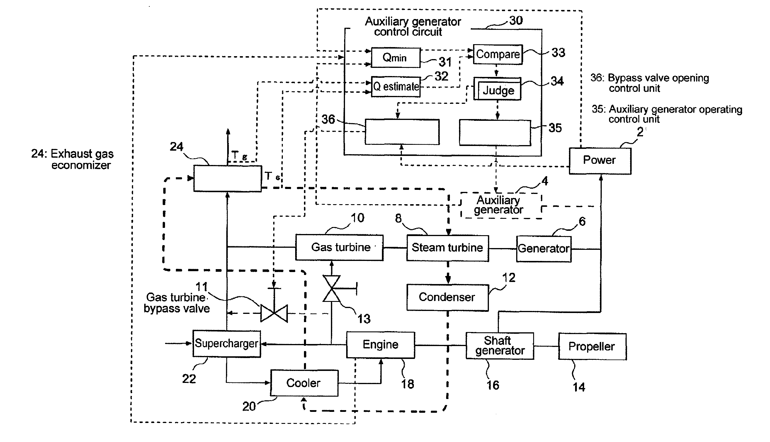
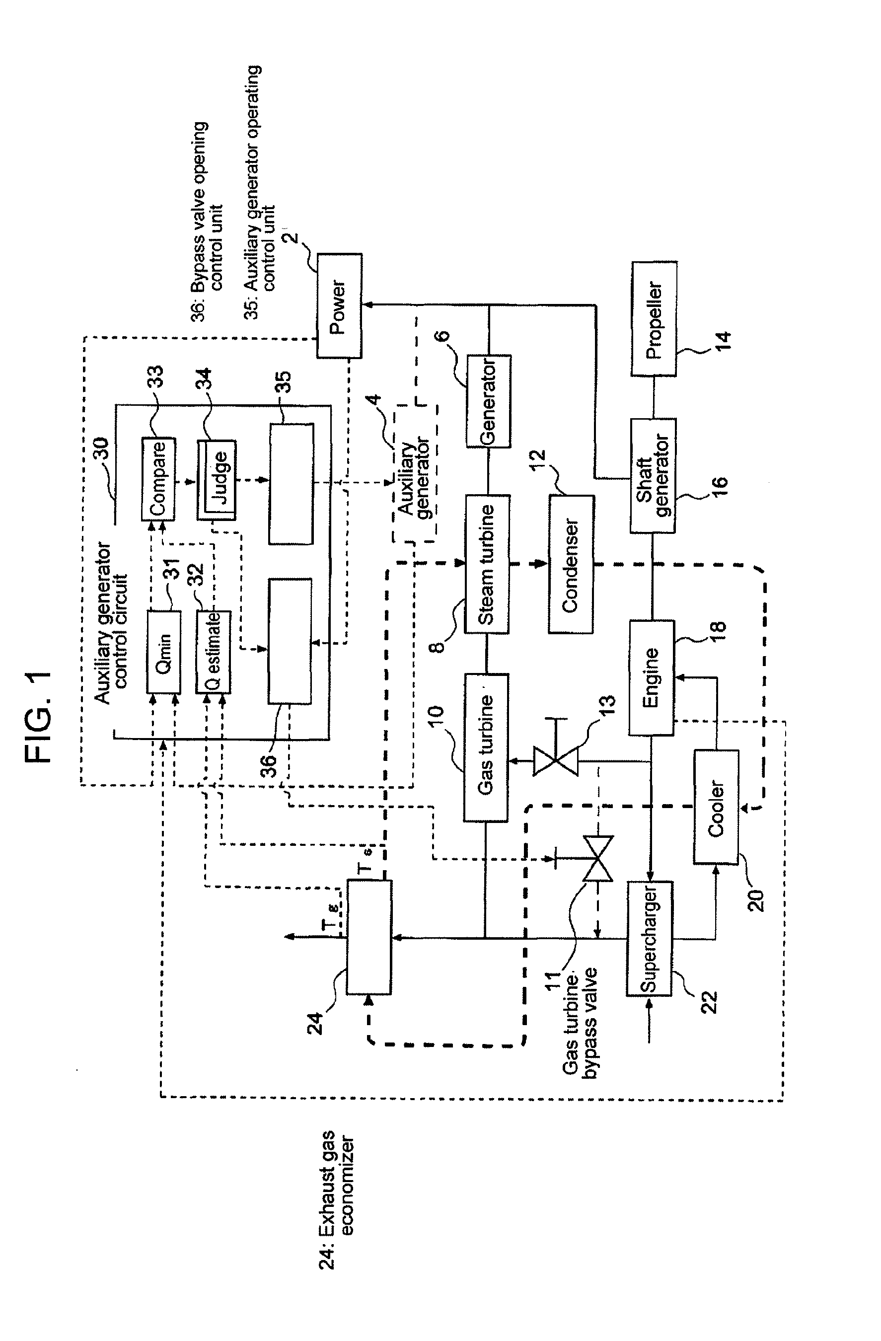
[0082]The electricity within the vessel is generated with use of the exhaust gas of the main engine (engine) of the vessel and thus, when there is a sudden decline of the power demand, the power having been generated becomes surplus. Then, the rotation of the gas turbine is accelerated, thereby causing damage thereof. To take measure against the issue caused by power surplus, a bypass valve opening control unit 36 controls the opening of the bypass valve 11 based on the power demand within the vessel by opening the bypass valve 11 fully and / or controlling the opening of the bypass valve 11 to bypass the gas turbine to supply the exhaust gas from the main engine (diesel engine).

[0083]In this state...


PUM


Abstract

Disclosed are a control method and a control device for an exhaust heat recovery system which are capable of preventing an onboard supply power outage in response to a sharp change in the load of the main drive machine. For an exhaust heat recovery system for which a portion of the exhaust gas generated by the ship's main drive machine is supplied to a gas turbine and the amount of heat of the exhaust gas exhausted by the gas turbine is conducted to an exhaust gas economizer, this control method and control device: obtain an estimated or calculated current reserve amount of heat (Q), which is based on the heat energy detection signal of the exhaust gas economizer; obtain, based on the operation state of an auxiliary electrical generator and on the onboard power demand, a reference amount of heat (Qmin), which is required to maintain the requisite power until the auxiliary electrical generator starts up; compare the current reserve amount of heat (Q) and the reference amount of heat (Qmin); and, based on the result of the comparison, select the operating state of the auxiliary electrical generator from either stop, idle or driving operation.

Description

BACKGROUND OF THE INVENTION[0001]1. Field of the Invention[0002]The present invention relates to a control method and a control device for an exhaust heat recovery system for a marine vessel, in particular, a control method and a control device for an exhaust heat recovery system which changes an operation state of an auxiliary generator based on a reserve heat amount of the exhaust gas economizer.[0003]2. Description of the Related Art[0004]As an exhaust heat recovery system for vessels, there is a power generation system wherein a steam turbine is driven by performing heat exchange with exhaust gas discharged from a main engine with use of an exhaust gas economizer which utilizes the exhaust gas from the main engine, and a system wherein the supply power is generated by rotating a shaft generator by engine output so as to compensate for electric power demand within the vessel. These types of systems have been proposed in view of saving power in the vessel.[0005]The exhaust heat re...

Claims


Application Information

Patent Timeline
IPC IPC(8): F02G5/02F02C9/00F02C6/00
CPCB63H21/32F01K15/045F01K23/10F02B41/10Y02T10/166F02C9/18F02G5/02Y02T70/5281Y02T10/163F02C6/00B63J2002/125Y02T10/12Y02T70/50B63H21/14B63J3/02F01D15/10
Inventor KAGIMOTO, YOSHIMIOHTA, YUJI
Owner MITSUBISHI HEAVY IND LTD
Why Eureka
Try Eureka