Solar Collector

a solar collector and solar energy technology, applied in the direction of solar heat collectors with working fluids, solar heat collectors for particular environments, etc., can solve the problems of affecting the efficiency of solar collectors, and inability to meet the needs of use, so as to reduce the chance of damage to the reflector, and reduce the effect of heat loss

Inactive Publication Date: 2011-08-25
SOLFAST
View PDF17 Cites 36 Cited by
  • Summary
  • Abstract
  • Description
  • Claims
  • Application Information

AI Technical Summary

Benefits of technology

[0124]Step a) (above) may comprise controlling the solar energy concentrator(s) so as to direct concentrated solar energy into the aperture. The solar energy concentrator(s) may comprise an array of reflectors in which case the step of controlling may comprise detecting a temperature at a position within the solar energy collector and, if necessary, orienting at least one of said reflectors to a non-collecting orientation so as to prevent said temperature exceeding a predetermined upper limit. The upper limit may be predetermined in order to prevent damage to materials of the solar energy collector. It may be predetermined to improve efficiency of the collector. The method may comprise passing a temperature related signal from one or more thermocouples disposed in the solar energy collector to a module controller. If necessary, a control signal may be generated in said module controller and sent to one or more motors. Each of the motors is coupled to one of the reflectors. This enables control of the orientation of the reflectors.
[0125]The method may additionally comprise controlling the solar energy concentrator(s) so that said concentrator(s) is (are) in a non-collecting orientation and inserting a plug so as to restrict loss of heat from the cavity of the solar energy collector when it is desired not to collect solar energy. In the case where the solar concentrator comprises a plurality of reflectors, the non-concentrating orientation may be one in which said reflectors are in a substantially horizontal orientation. This minimises the chance of damage to the reflectors from high wind gusts when they are not in use. The plug may be inserted into the aperture of the solar energy collector or into the shield aperture in the shield (if present).

Problems solved by technology

There are a number of barriers to the increased use of renewable energy.
The major barriers are that renewable energy sources are, in the main, costlier than other energy sources, are not available at the times required and are of variable quality.
It is a feature of these linear systems that maximum temperatures consistently achievable are in the range of 350° C., which means that the heat engines operate at low efficiency levels, i.e. in the 250° C. to 300° C. range.

Method used


Image

  • Solar Collector
  • Solar Collector
  • Solar Collector

Examples


Embodiment Construction

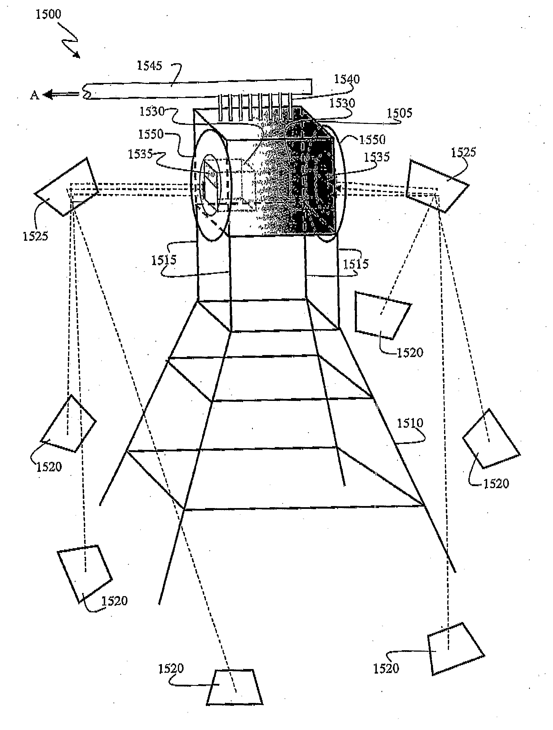
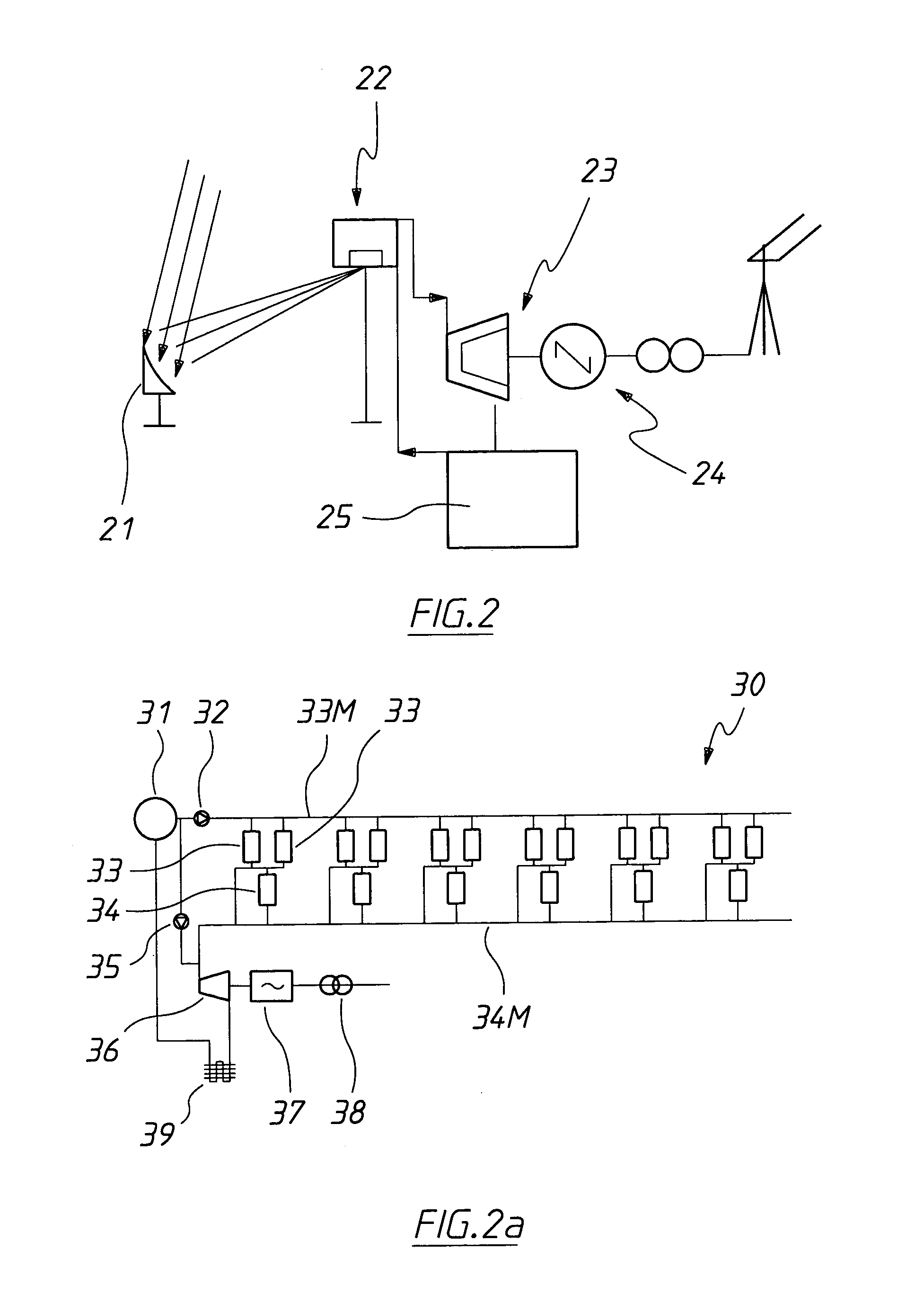
[0164]The present invention relates to a solar collector, and to a solar energy collection device comprising a solar energy concentrator and the solar collector. In particular it relates to collecting concentrated solar thermal energy and controlling the time of transfer of that thermal energy to a heat exchanger system prior to its extraction for subsequent use. The concentrator and the collector may be disposed so that solar energy impinging on the concentrator is concentrated on a collection region of the collector. The energy so collected may then be transferred from the heat transfer material in the collector to a heat transfer fluid in the heat exchanger.

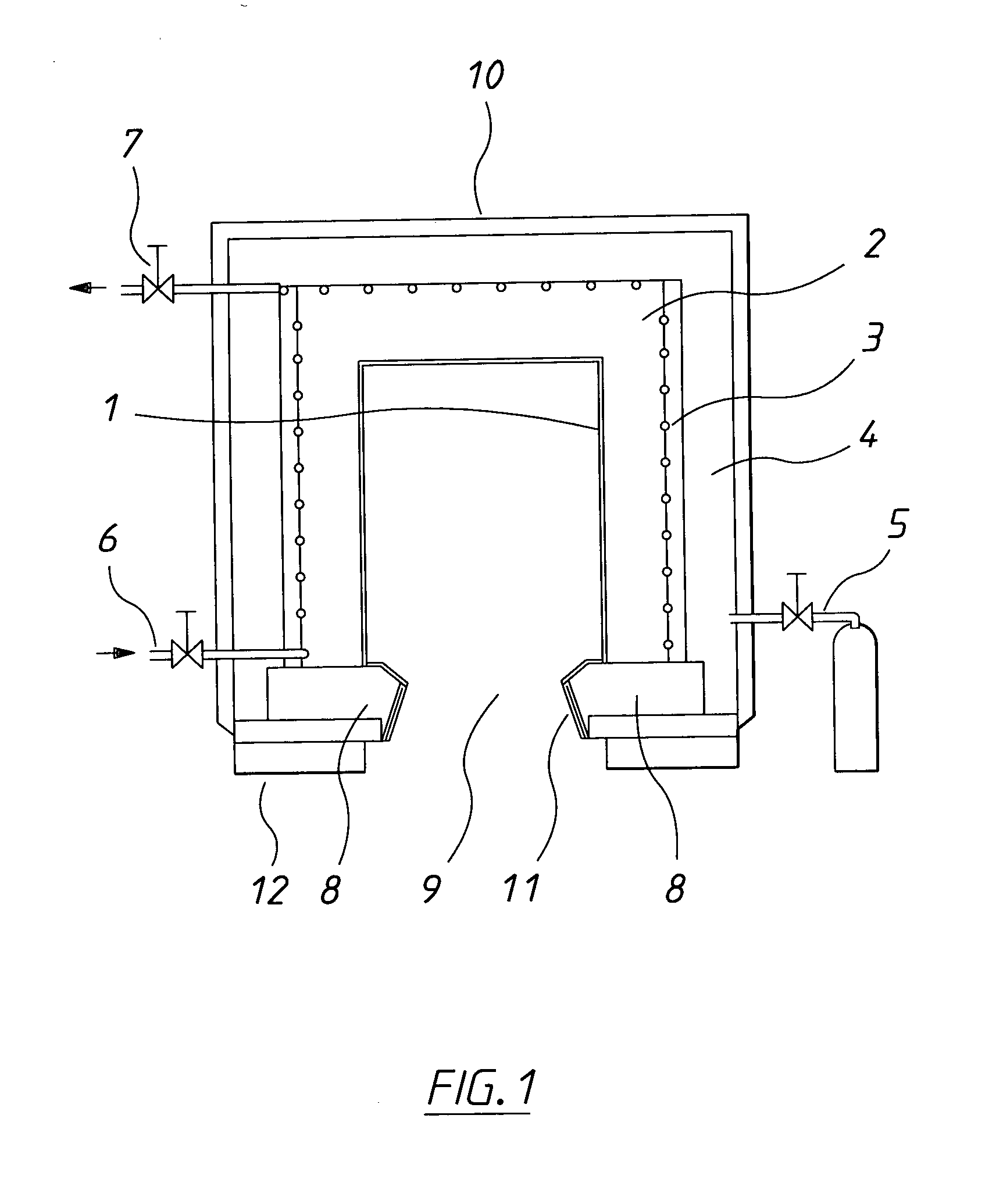
[0165]The heat regulating medium may be a solid. Suitable heat regulating solids commonly have a high carbon content. Suitable materials include for example graphite, graphite particles embedded in a thermally conductive matrix such as a metallic matrix (e.g. copper, gold, aluminium, silver, mixtures or alloys of any two or mo...


PUM


Abstract

The invention relates to a solar collector. The collector has a heat regulating medium which defines a cavity therein. An aperture communicates with the cavity so as to allow solar energy incident on the aperture to enter the cavity. An energy collection device is disposed in the cavity and in thermal contact with the heat regulating medium to collect solar energy entering the cavity.

Description

TECHNICAL FIELD[0001]The present invention relates to a device for collecting and regulating solar energy.BACKGROUND OF THE INVENTION[0002]There exists a well recognized need worldwide to increase the use of renewable energy sources and reduce the amount of fossil fuels consumed in energy production.[0003]There are a number of barriers to the increased use of renewable energy. The major barriers are that renewable energy sources are, in the main, costlier than other energy sources, are not available at the times required and are of variable quality. Hence there exists a need for regulating systems which can help bridge the time gap between availability and demand and also maintain the quality of the electricity produced from renewable sources. In this way the renewable energy would become more inherently valuable. Adding value to renewable energy by improving its quality and making it available on demand would substantially help to overcome the higher capital cost of systems and the...

Claims


Application Information

Patent Timeline
Patent Type & Authority Applications(United States)
IPC IPC(8): F24J2/10F24J2/24F24J2/48F24J2/38F24J2/40F03G6/00F24J2/46F24S10/70F24S20/20F24S23/00F24S23/70F24S50/20
CPCY02E10/46Y02E10/41F24J2/07F24J2/10F24J2002/003F24J2/4609F24J2/4623F24J2/51F24J2/34F24S80/60F24S40/52F24S40/10F24S23/70F24S20/20F24S2023/88F24S60/30F24S2070/62Y02P90/50Y02E10/40
Inventor HOLLIS, STEPHENGENTLE, RICHARD HOWARD
Owner SOLFAST
Why Eureka
Try Eureka