Photovoltaic Cell Module And Method Of Forming

a photovoltaic cell and module technology, applied in the direction of chemistry apparatus and processes, sustainable manufacturing/processing, final product manufacturing, etc., can solve the problems of increasing cost, slow and inefficient process, difficult to control the thickness of the tie layer, etc., to reduce the flammability of the module, reduce the loss or leakage of silicone composition, and provide structural strength

Inactive Publication Date: 2011-08-25
HOWELL MALINDA +3
View PDF27 Cites 34 Cited by
  • Summary
  • Abstract
  • Description
  • Claims
  • Application Information

AI Technical Summary

Benefits of technology

[0005]A photovoltaic cell module is formed by a method of this invention. In one embodiment, the method includes the steps of disposing the photovoltaic cell on the first outermost layer, disposing a silicone composition on the photovoltaic cell, at least partially coating a plurality of fibers with the silicone composition to form a second layer, and compressing the first outermost layer, the photovoltaic cell, and the second layer to form the module. Relative to this embodiment, the plurality of fibers extends laterally across the second layer to a periphery of the module on both ends of the module. As such, the plurality of fibers is able to resist leakage of the silicone composition from the module during the step of compressing.
[0006]The second (outermost) layer allows the photovoltaic cell to be secured within the module while simultaneously minimizing an amount of the silicone composition that must be used. If utilized, the plurality of fibers of the second (outermost) layer controls dispersion of the silicone composition and a resulting thickness of the module and also minimizes loss or leakage of the silicone composition outside of the module such as during the step of compressing. The plurality of fibers, in conjunction with the silicone composition, also provides structural strength to the module, decreases flammability of the module, and increases adhesion strength between the photovoltaic cell and the first outermost layer. The plurality of fibers and the silicone composition also allow the module to be rigid, semi-rigid, or flexible while maintaining electrical efficiency and structural integrity. Still further, the plurality of fibers allows for cost effective and repeatable production of the module because of controlled diffusion of the silicone composition, minimization of the amount of silicone composition used, minimized waste, and increased consistency of thickness and size of the module. The plurality of fibers and the silicone composition also allow for formation of a module without a supporting layer thereby reducing costs, production complexities, and time needed to form the module.

Problems solved by technology

These types of modules are usually made using processes that are slow and inefficient due to a need to control the dispersion of the tie layers and to minimize leakage of the tie layers from the substrates and superstrates to reduce waste.
In both types of modules, it is difficult to control a thickness of the tie layers because the tie layers can flow across the substrates and superstrates in inconsistent patterns.
Additionally, methods of forming both types of modules results in increased expense, increased processing times, and increased processing complexity.
These all result in increased cost for the end purchaser.

Method used


Image

  • Photovoltaic Cell Module And Method Of Forming
  • Photovoltaic Cell Module And Method Of Forming
  • Photovoltaic Cell Module And Method Of Forming

Examples


examples

Formation of Modules:

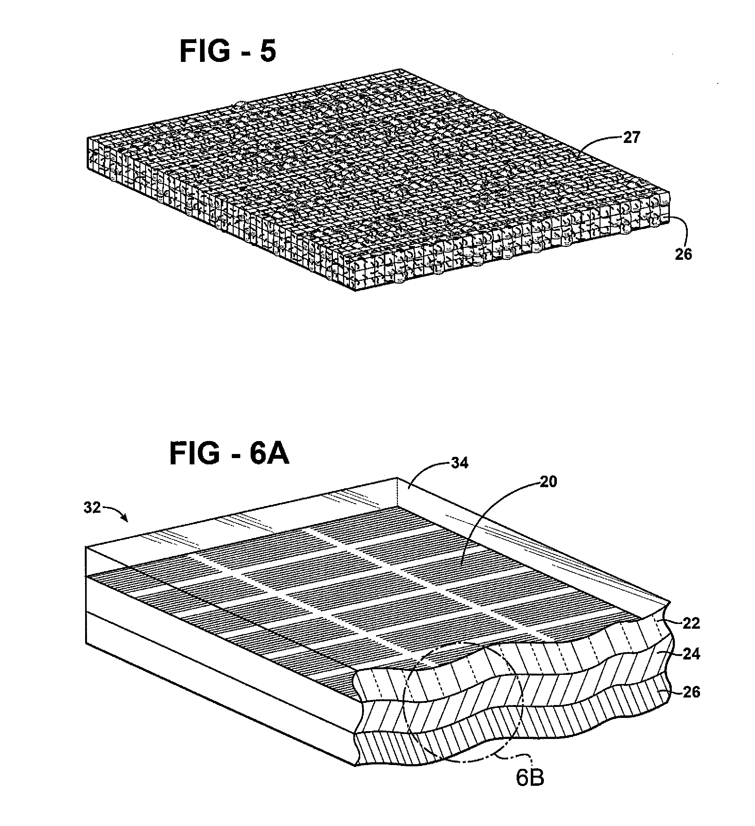
[0153]Two modules (Modules A and B) are formed according to the method of instant invention. In addition, four comparative modules (Comparative Modules A-D) are also formed but not according to the method of the instant invention. In the Modules A and B, a plurality of fibers extends laterally across a second layer to a periphery of the Modules on both ends of the Modules.

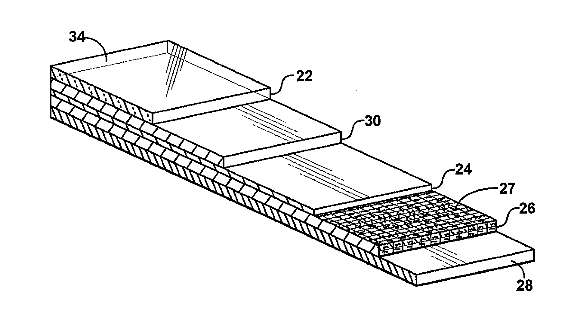
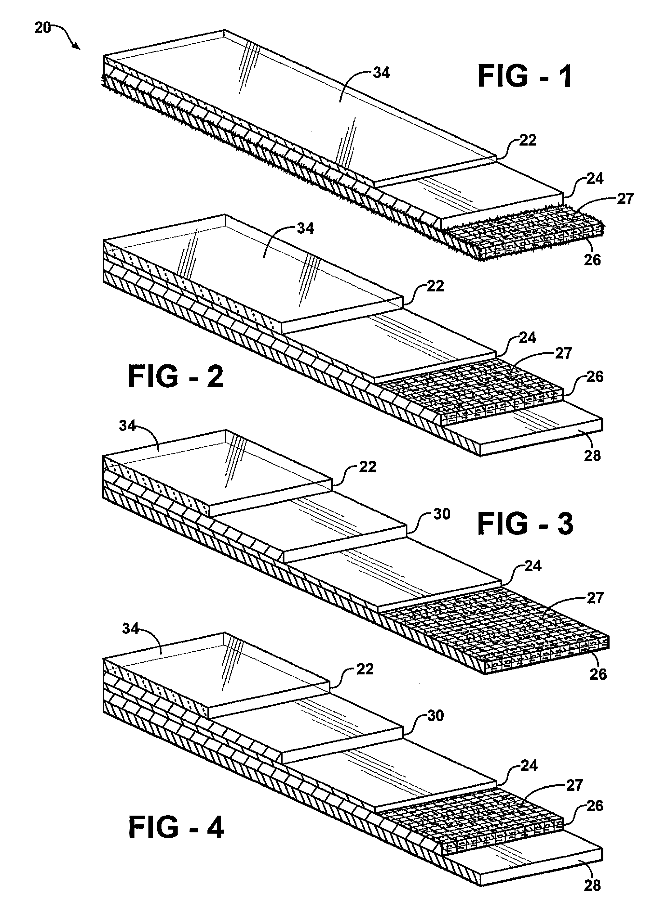
[0154]More specifically, Module A includes:

[0155]A 156 mm×156 mm×3.2 mm first outermost layer (glass) having a light transmittance of at least 70 percent as determined by UV / Vis spectrophotometry using ASTM E424-71;

[0156]A 156 mm×156 mm×200 μm photovoltaic cell disposed on the first outermost layer;

[0157]A 5-mil second layer uniformly disposed on and across the photovoltaic cell and including a textile (non-woven fiberglass) as the plurality of fibers that is at least partially coated with a first liquid silicone composition; and

[0158]A 156 mm×156 mm×125 μm supporting layer (Tedlar®) disposed o...


PUM

PropertyMeasurementUnit
light transmittanceaaaaaaaaaa
thicknessaaaaaaaaaa
light transmittanceaaaaaaaaaa

Abstract

A photovoltaic cell module, a photovoltaic array including at least two modules, and a method of forming the module are provided. The module includes a first outermost layer and a photovoltaic cell disposed on the first outermost layer. The module also includes a second outermost layer disposed on the photovoltaic cell and sandwiching the photovoltaic cell between the second outermost layer and the first outermost layer. The method of forming the module includes the steps of disposing the photovoltaic cell on the first outermost layer, disposing a silicone composition on the photovoltaic cell, and compressing the first outermost layer, the photovoltaic cell, and the second layer to form the photovoltaic cell module.

Description

FIELD OF THE INVENTION[0001]The present invention generally relates to a photovoltaic cell module and a photovoltaic array. More specifically, the present invention relates to a photovoltaic cell module including a first outermost layer, a photovoltaic cell, and a second outermost layer that has particular properties and that is disposed on the photovoltaic cell sandwiching the photovoltaic cell between the second outermost layer and the first outermost layer. The present invention also relates to a method of forming a photovoltaic cell module.DESCRIPTION OF THE RELATED ART[0002]Solar or photovoltaic cells are semiconductor devices used to convert light into electricity. There are two general types of photovoltaic cells, wafers and thin films. Wafers are thin sheets of semiconductor material that are typically formed from mechanically sawing the wafer from a single crystal or multicrystal ingot. Alternatively, wafers can be formed from casting. Thin film photovoltaic cells usually i...

Claims


Application Information

Patent Timeline
Patent Type & Authority Applications(United States)
IPC IPC(8): H01L31/0203H01L31/18
CPCB32B17/10018B32B17/10798B32B2327/12H01L31/02167H01L31/049H01L31/18Y02E10/542Y02E10/549H01L31/0481H01L31/048Y02P70/50
Inventor HOWELL, MALINDAJUEN, DONNIEKETOLA, BARRYTOMALIA, MARY KAY
Owner HOWELL MALINDA
Why Eureka
Try Eureka