Device for evaporating a treatment liquid

Inactive Publication Date: 2011-08-25
SERAC GROUP
View PDF14 Cites 7 Cited by
  • Summary
  • Abstract
  • Description
  • Claims
  • Application Information

AI Technical Summary

Benefits of technology

[0005]An object of the invention is to propose a device that is of simple structure and that enables a treatment gas to be extracted from a treatment liqui

Problems solved by technology

Nevertheless, in order to ensure that all of the solution is in the vapor state, it is necessary to provide a tube of great length, thereby giving rise to an installation that is bulky.
In addition, the solution deposits solid residues inside the tube, wh

Method used


Image

  • Device for evaporating a treatment liquid
  • Device for evaporating a treatment liquid
  • Device for evaporating a treatment liquid

Examples


Embodiment Construction

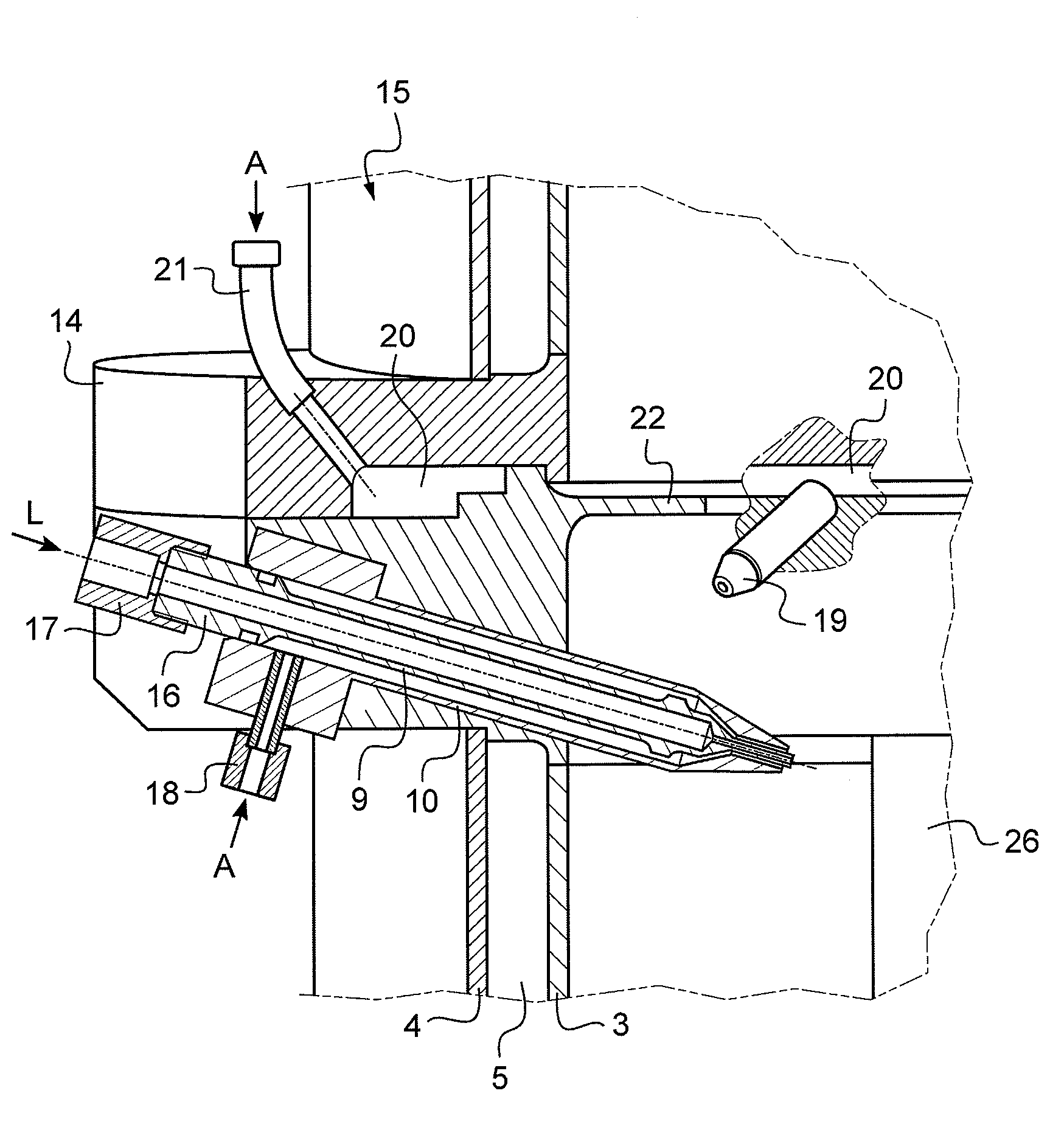
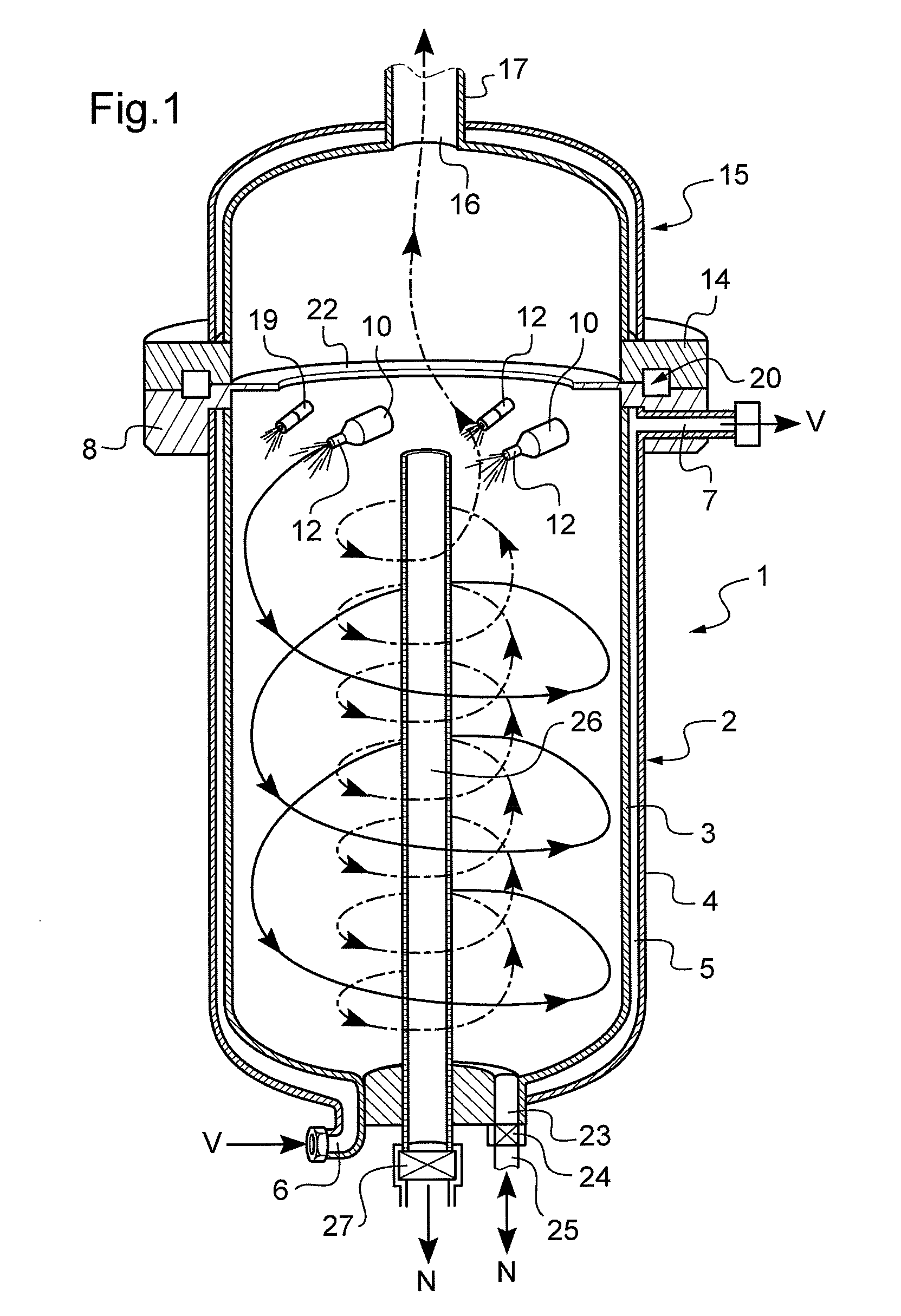
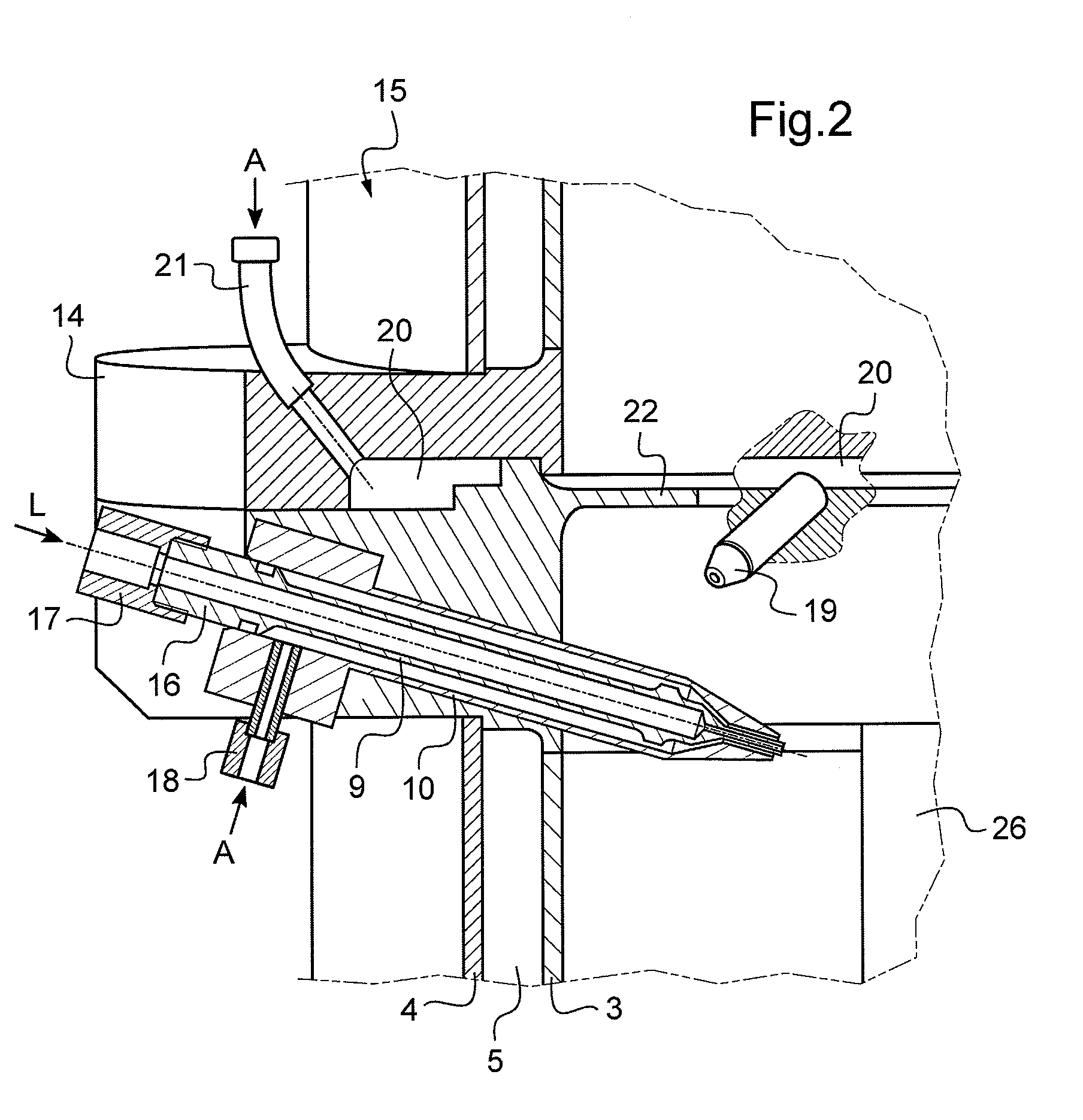
[0013]With reference to the figures, the device of the invention comprises a cylindrical enclosure 1 of circular right section having a concave bottom, here of curvilinear shape. The side wall 2 is made in the form of a double wall having an inside wall 3 and an outside wall 4 defining between them a space 5.

[0014]The space 5 is closed at its top end by an annular ring 8 that also serves as a support for means for introducing treatment liquid of structure that is described in detail below.

[0015]A flow of steam is established in the space 5 by introducing steam V via a steam introduction coupling 6 at the base of the enclosure and the steam V is extracted therefrom via a steam outlet coupling 7 carried by the ring 8 in an angular position that is offset from the coupling 6, that is diametrically opposite in this example, so as to force the stream to flow around the inside wall 3 inside the space 5 between the inside wall 3 and the outside wall 4 by moving helically.

[0016]The ring 8 i...


PUM


Abstract

The device for evaporating a treatment liquid comprises a cylindrical enclosure having an outlet orifice opening out into the top end of the enclosure, the enclosure being placed vertically and having a heated inside wall, and liquid nozzles associated with a blow pipe for blowing air under pressure so as to form a jet comprising a mixture of air and of pulverized treatment liquid in a direction that is tangential to the inside wall of the enclosure, each liquid nozzle and the associated blow pipe being arranged so that the jet of mixture is formed in an upper portion of the enclosure and is downwardly inclined.

Description

[0001]The present invention relates to a device for evaporating a treatment liquid, and particularly but not exclusively, to a device for extracting hydrogen peroxide from a solution of hydrogen peroxide.BACKGROUND OF THE INVENTION[0002]Hydrogen peroxide is known for use in particular for sterilizing containers prior to aseptic filling of the containers. Nevertheless, hydrogen peroxide is considered as being a pollutant and precise standards therefore exist concerning the residual quantities thereof that are acceptable when the container is to contain foodstuffs. In order to satisfy those standards, containers must be treated with a treatment gas that is free from any droplets of liquid.[0003]It is known to extract hydrogen peroxide from a hydrogen peroxide solution by causing the solution to evaporate. In particular, it is known from document U.S. Pat. No. 4,631,173 to spray a solution of hydrogen peroxide into a flow of air and then to put the resulting stream into contact with th...

Claims


Application Information

Patent Timeline
IPC IPC(8): B01D1/20
CPCB01D1/16B01D1/305B01D1/22
Inventor GRUSON, BERTRAND
Owner SERAC GROUP
Why Eureka
Try Eureka