Liquid ejecting head

Active Publication Date: 2011-08-25
SEIKO EPSON CORP
View PDF6 Cites 20 Cited by
  • Summary
  • Abstract
  • Description
  • Claims
  • Application Information

AI Technical Summary

Benefits of technology

[0018]Accordingly, the inclination angle of the terminal is configured to increase as the terminal becomes more distant from the individual electrode terminals located in the center portion in th

Problems solved by technology

This may cause a problem, such as a connection failure due to short circuit between adjacent wires.
As a result, it may be displaced from a predetermined connection position between the flexible cable terminals and the pressure generating element terminals, thereby c

Method used


Image

  • Liquid ejecting head
  • Liquid ejecting head
  • Liquid ejecting head

Examples


first embodiment

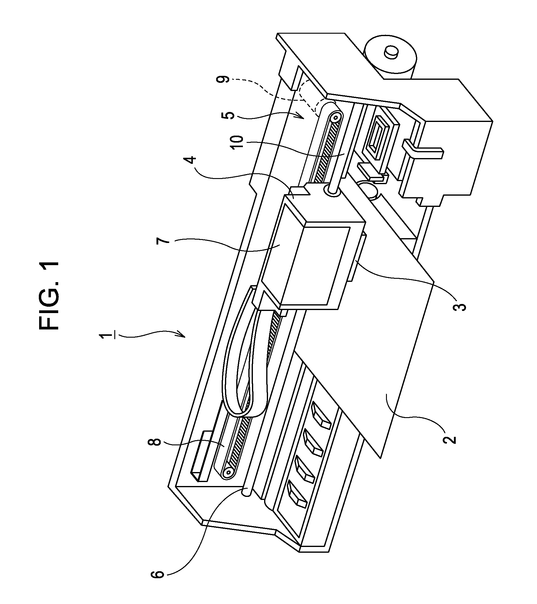
[0028]First, a general configuration of a printer is explained with reference to FIG. 1. A printer 1 is an apparatus that performs recording of images and the like by ejecting ink in a liquid form to a surface of a recording medium 2 such as a recording sheet. The printer 1 includes a recording head 3 that ejects ink, a carriage 4 on which the recording head 3 is mounted, a carriage movement mechanism 5 that moves the carriage 4 in a primary scanning direction, a platen roller 6 that moves the recording medium 2 in a secondary scanning direction. Here, the above-mentioned ink is a type of liquid of the invention, which is stored in an ink cartridge 7. The ink cartridge 7 is removably attached to the recording head 3. A configuration may also be employed in which the ink cartridge 7 is disposed on the body of the printer 1 such that ink is supplied from the ink cartridge 7 to the recording head 3 via an ink supply tube.

[0029]The carriage movement mechanism 5 includes a timing belt 8...

second embodiment

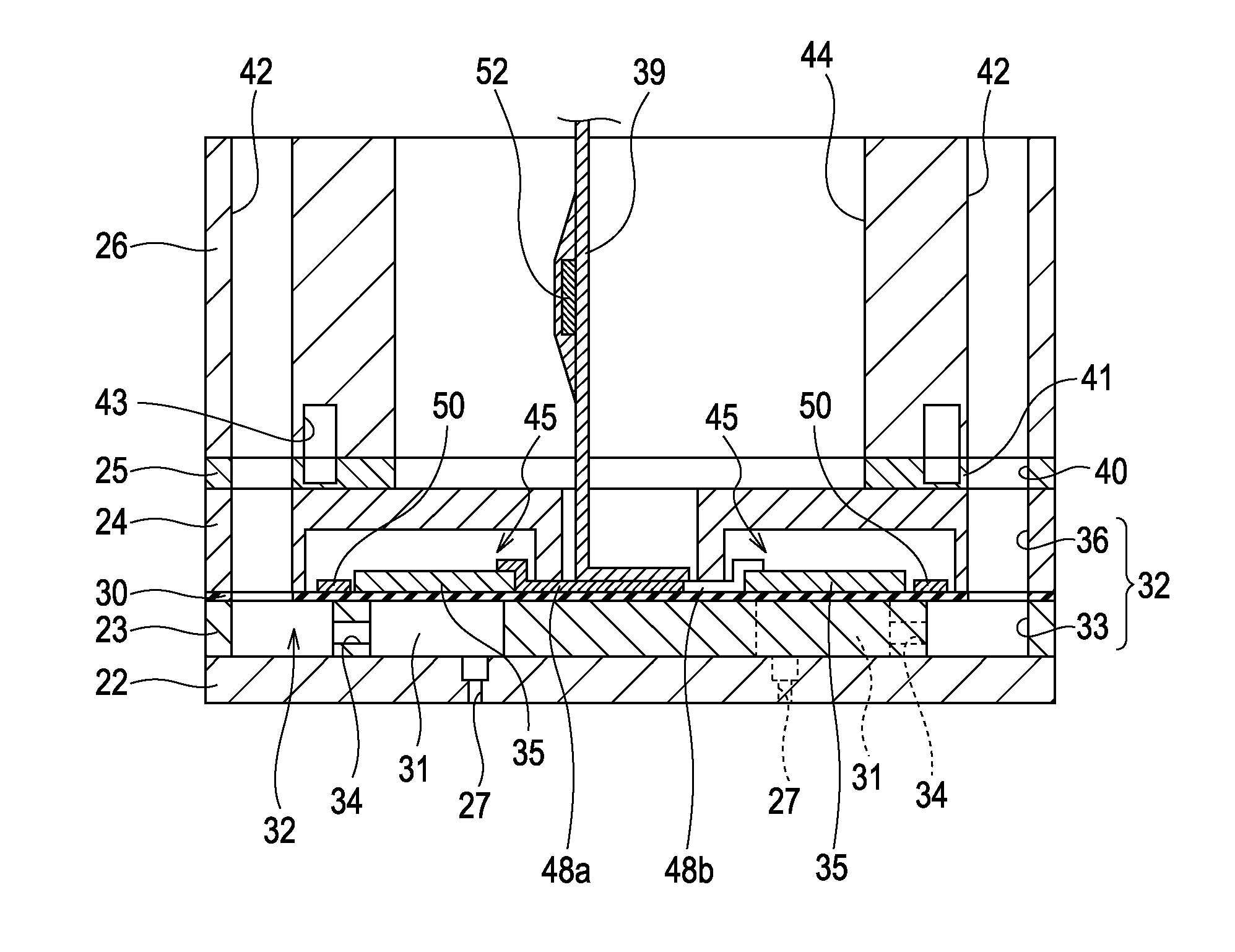
[0045]Further, the individual element electrode terminals 48 (a type of individual electrode terminal) each having a strip shape in plan view and electrically connected to the corresponding individual element electrodes 47 are disposed in a plurality of rows lying in the direction of the row of the pressure chambers 31 (the nozzle row direction) between the adjacent nozzle rows. More specifically, the individual element electrode terminals 48 include center individual element electrode terminals 48A which are located in the center portion in the terminal row direction (the same direction as the nozzle row direction, indicated by an arrow X in FIG. 5) and side individual element electrode terminals 48B which are located in the side portion in the terminal row direction X. The center individual element electrode terminals 48A extend in the direction perpendicular to the terminal row direction X. On the other hand, the side individual element electrode terminals 48B are bent, with the ...


PUM


Abstract

A liquid ejecting head that can be of reduced size while maintaining reliability of the terminal connection is provided. According to the liquid ejecting head of the invention, individual element electrode terminals and first side individual electrode wiring terminals of a flexible cable, which are connected to the individual element electrode terminals are arrayed in a direction of a row of pressure chambers, and at least one of a side individual element electrode terminals located in a side portion in a terminal row direction X and a first side individual electrode wiring terminals connected to the side individual element electrode terminals are arranged inclined with respect to a center individual element electrode terminals located in the center portion in the terminal row direction.

Description

[0001]The entire disclosure of Japanese Patent Application No: 2010-034705, filed Feb. 19, 2010 are expressly incorporated by reference herein.BACKGROUND[0002]1. Technical Field[0003]The present invention relates to liquid ejecting heads such as ink jet recording heads that eject liquid droplets from nozzles by means of pressure variation.[0004]2. Related Art[0005]The liquid ejecting heads that eject liquid droplets from nozzles by varying a pressure of the liquid in a pressure chamber include, for example, ink jet recording heads (hereinafter simply referred to as recording heads) used for image recording apparatuses such as ink jet recording apparatuses (hereinafter simply referred to as printers), color material ejecting heads used for manufacturing color filters for liquid crystal displays and the like, electrode material ejecting heads used for forming electrodes for field emission displays (FEDs), organic electroluminescence (EL) displays and the like, and bioorganic ejecting ...

Claims


Application Information

Patent Timeline
IPC IPC(8): B41J2/045
CPCB41J2/14233B41J2002/14491B41J2002/14362
Inventor MIYATA, YOSHINAOGAO, YUEFUKUZAWA, YUMA
Owner SEIKO EPSON CORP
Why Eureka
Try Eureka