Pressure damper, liquid jet head, and liquid jet apparatus

a technology of liquid jet and damper, which is applied in the direction of spraying apparatus, spraying nozzle, printing, etc., can solve the problems of increasing the pressure loss due to the flow path, and achieve the effect of reducing the fluid pressure fluctuations and reducing the pressure fluctuations

Inactive Publication Date: 2011-08-25
SII PRINTEK
View PDF4 Cites 22 Cited by
  • Summary
  • Abstract
  • Description
  • Claims
  • Application Information

AI Technical Summary

Benefits of technology

[0029]The pressure damper according to the present invention includes: a main body portion, the main body portion including a recessed portion with an opening and a communication hole which is open to an inner surface of the recessed portion and communicates to an external region; a flexible thin film which closes the opening for reducing pressure fluctuations of fluid enclosed in the recessed portion; and a detecting portion engaged with the main body portion for detecting electromotive force generated by electromagnetic induction thereby detecting relative positional change between the flexible thin film and the main body portion. With this, the pressure damper according to the present invention has an advantage that, when pressure fluctuations are caused in fluid enclosed in the recessed portion, the flexible thin film reduces the pressure fluctuations, and, based on the positional fluctuations of the flexible thin film, pressure fluctuations of fluid may be detected.

Problems solved by technology

However, when the length of the tube becomes larger, the flow path resistance of liquid which flows therein increases and the pressure loss due to the flow path increases.

Method used


Image

  • Pressure damper, liquid jet head, and liquid jet apparatus
  • Pressure damper, liquid jet head, and liquid jet apparatus
  • Pressure damper, liquid jet head, and liquid jet apparatus

Examples


first embodiment

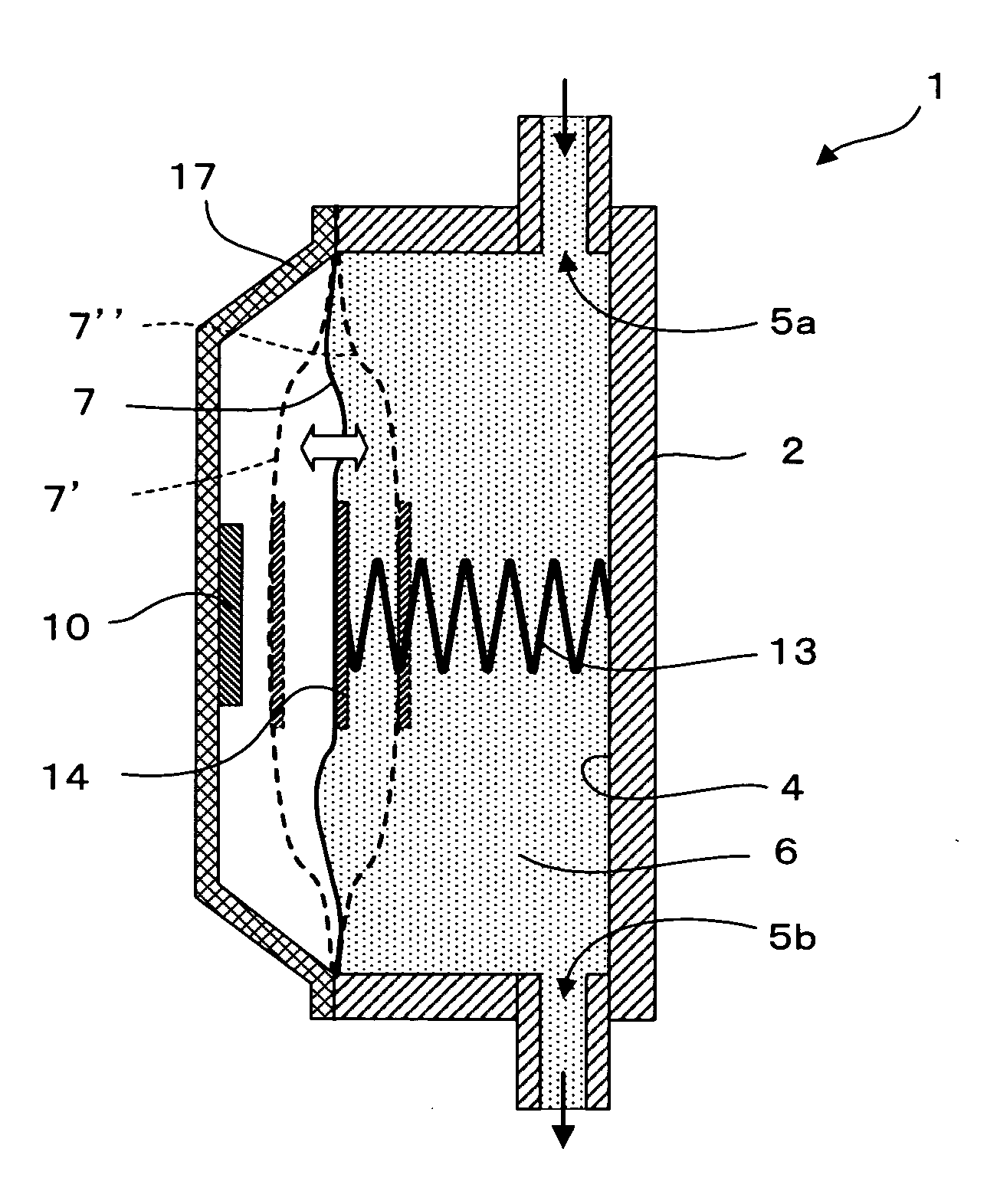
[0052]FIG. 1 is a schematic longitudinal sectional view of a pressure damper 1 according to a first embodiment of the present invention. The pressure damper 1 includes a main body portion 2 having a recessed portion 4 for keeping fluid therein and a communication hole 5a and a communication hole 5b which are open in an inner wall surface of the recessed portion 4, a flexible thin film 7 which closes an opening of the main body portion 2 and which is flexible, a cover 17 placed on the main body portion 2 so as to cover an outer surface of the flexible thin film 7, a reference member 14 engaged with the recessed portion 4 side of the flexible thin film 7, an elastic member 13 one end of which is engaged with the reference member 14 and the other end of which is engaged with a bottom surface of the recessed portion 4, and a detecting portion 10 placed on the flexible thin film 7 side of the cover 17.

[0053]The recessed portion 4 enclosed by the flexible thin film 7 includes fluid 6 ther...

second embodiment

[0063]FIG. 4 is a schematic longitudinal sectional view of the pressure damper 1 according to a second embodiment of the present invention. The second embodiment differs from the first embodiment in that a magnetic sheet 19 is provided between the cover 17 and the detecting portion 10, and other structures are similar to those in the first embodiment. Therefore, in the following, the different structure is described in the following and description of similar structures is omitted. Note that, like reference symbols are used to designate like members or members having like functions.

[0064]As illustrated in FIG. 4, the magnetic sheet 19 which is to be a magnetic path is placed between the cover 17 and the detecting portion 10. This prevents magnetic lines of force generated by the detecting portion 10 from reaching the cover 17, and the magnetic lines of force pass through the magnetic sheet 19. Even if a conductive metallic material is used as the cover 17, a loss due to eddy current...

third embodiment

[0066]FIG. 5 is a schematic sectional view of the pressure damper 1 according to a third embodiment of the present invention. The third embodiment differs from the first and second embodiments in that a position regulating portion 15 for regulating the position of the other end of the elastic member 13 is provided between the other end of the elastic member 13 and the main body portion 2, and other structures are similar to those in the second embodiment.

[0067]As the elastic member 13, a coil spring is used. The screw-in position regulating portion 15 is provided between the coil spring and the main body portion 2. As a result, the position of the reference member 14 is regulated according to the kind, the viscosity, and the internal pressure of the fluid 6, or according to tolerances of the elastic member 13, the reference member 14, the flexible thin film 7, the main body portion 2, and the like. Note that, the position regulating portion 15 illustrated in FIG. 5 is only exemplary...


PUM


Abstract

Provided is a pressure damper reducing pressure fluctuations of liquid and detecting the pressure fluctuations of the liquid. The pressure damper (1) includes: a main body portion (2), the main body portion (2) including a recessed portion (4) with an opening and a communication hole (5) which is open to an inner surface of the recessed portion (4) and communicates to an external region; a flexible thin film (7) which closes the opening for reducing pressure fluctuations of fluid (6) included in the closed recessed portion (4); and a detecting portion (10) engaged with the main body portion (2) for detecting electromotive force generated by electromagnetic induction thereby detecting relative positional change between the flexible thin film (7) and the main body portion (2).

Description

BACKGROUND OF THE INVENTION[0001]1. Field of the Invention[0002]The present invention relates to a pressure damper for reducing pressure fluctuations of fluid, and more particularly, to a pressure damper having a function of converting pressure fluctuations of fluid into an electrical signal, and a liquid jet head and a liquid jet apparatus using the same.[0003]2. Description of the Related Art[0004]In recent years, there has been used an ink jet type liquid jet head for discharging ink droplets on recording paper or the like to render a character or a graphics or for discharging a liquid material on a surface of an element substrate to form a functional thin film. In such a liquid jet head, ink or a liquid material is supplied from a liquid tank via a supply tube to the liquid jet head, and the ink or the liquid material filled into a channel is discharged from a nozzle which communicates to the channel. When the ink is discharged, the liquid jet head or a recording medium on which...

Claims


Application Information

Patent Timeline
Patent Type & Authority Applications(United States)
IPC IPC(8): B41J2/175B05B1/08
CPCB41J2/17513B41J2/01B41J2/045B41J2/175
Inventor SAGA, YUKIHIROWATANABE, TOSHIAKI
Owner SII PRINTEK
Why Eureka
Try Eureka