Aperture stop

Active Publication Date: 2011-08-25
VS TECH CORP
View PDF3 Cites 21 Cited by
  • Summary
  • Abstract
  • Description
  • Claims
  • Application Information

AI Technical Summary

Benefits of technology

[0018]According to the aperture stop of the present invention, the aperture area is formed inside the filter area that transmits light in the wavelength range corresponding to fluorescent light from an observed area of a subject, and reduces or blocks light in the wavelength range corresponding to illumination light to the subject. Thus, only the light in the wavelength range of illumination light forming the subject image is reduced without reducing the fluorescent light from the observed area of the subject. Therefore, even when the light amount of light in the wavelength range of illumination light forming the subject image is predominantly greater than that of weak fluorescent light from the observed area of the subject, it is possible to clearly observe the observed image formed by weak fluorescent light while preventing the observed image formed by weak fluorescent light from being lost in the subject image formed by the illumination light.
[0019]Moreover, according to the aperture stop of the present invention, light forming a subject image formed by illumination light is reduced by the aperture area. Therefore, according to an imaging device including the aperture stop of the present invention, the focal depth is increased for th

Problems solved by technology

However, the fluorescent light emitted from the light-sensitive substance is extremely weak as compared with the illumination light, thereby causing such a problem that a fluorescent light image is lost in the subject image formed by the illumination light.
With this method, however, there is a problem that the fluorescent light image is lost in the subject image.
With this method, however, since not only fluorescent light in the infrared region but also light of the R component forming the subject image are emphasized simultaneously, it becomes difficult to accurately observe the area emitting fluorescent light in the subject image.
Moreover, there is another problem such that it is required to provide a filter for separating the subject image into RGB components and a filter driving mechanism, thereby complicating the device configuration.
However, in the case where such an illuminator is used, not for endoscopic observation, but for observing tissues exposed to the strong illumi

Method used


Image

  • Aperture stop
  • Aperture stop
  • Aperture stop

Examples


Example

[0033]Hereinafter, the present invention will be described in detail with reference to the drawings. Note that in the drawings, the same reference numerals refer to the same or like elements.

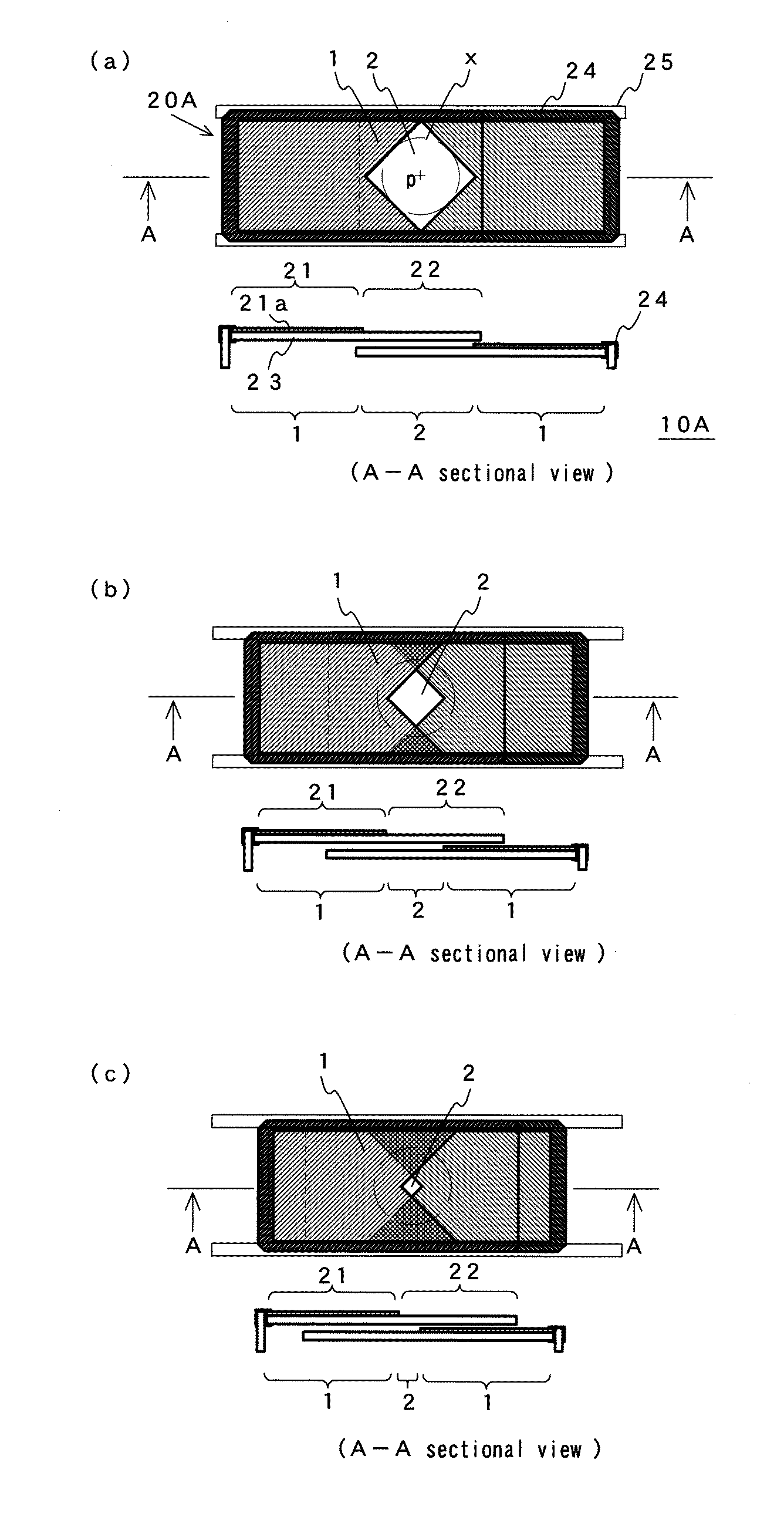
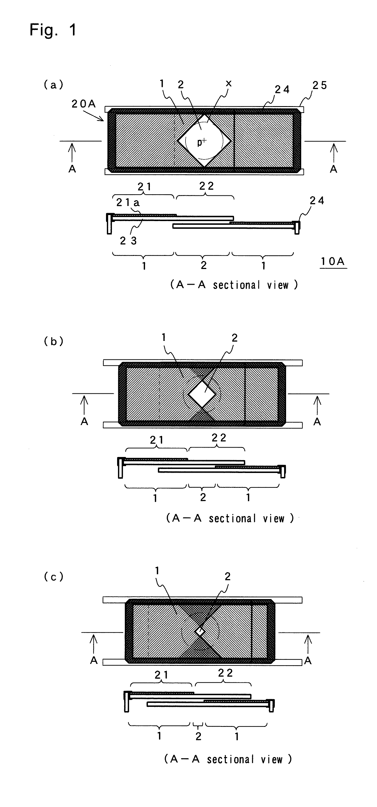
[0034]FIG. 1 is a diagram illustrating a two-blade type aperture stop 10A, which is an aperture stop according to an embodiment of the present invention. FIG. 2 is a plan view showing a pair of stop blade members 20A of the two-blade type aperture stop 10A.

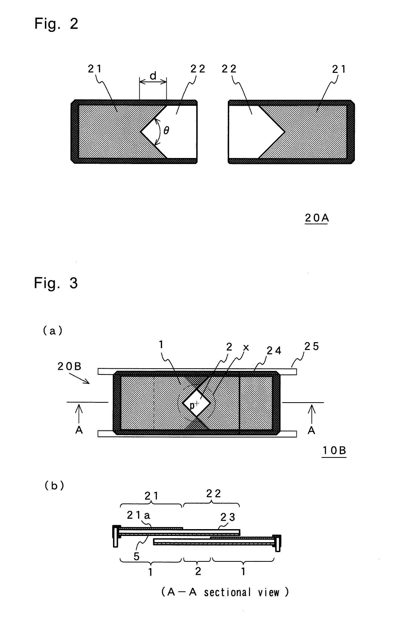
[0035]The stop blade member 20A includes a filter portion 21 on which a filter layer 21a is formed and a non-filter portion 22 that is an area on which the filter layer 21a is not formed. The filter portion 21 and the non-filter portion 22 are provided respectively at the left half and right half of the surface of a rectangular flat-plate substrate 23. The stop blade member 20A is fitted into an outer frame 24. Herein, the filter layer 21a has a V-shaped reentrant portion on the side of the non-filter portion 22. The filter layer 21a transmits...


PUM


Abstract

An aperture stop 10A includes a filter area 1 formed on a flat-plate substrate 23, and an aperture area 2 formed inside the filter area 1. The filter area 1 transmits infrared light and reduces or blocks the transmission of visible light. The aperture area 2 transmits light in the wavelength range corresponding to fluorescent light from an observed area of a subject and light in the wavelength range corresponding to illumination light to the subject. The aperture stop 10A does not reduce the light in the wavelength range corresponding to fluorescent light from the observed area of the subject, but variably reduces visible light since the area of the aperture area 2 is variable. Therefore, it becomes possible to simultaneously and clearly observe, with a simple method, a subject image formed by illumination light in the visible light band and an observed image formed by weak fluorescent light from the observed area of the subject in the infrared light band.

Description

TECHNICAL FIELD[0001]The present invention relates to an aperture stop used for simultaneously and clearly capturing an observed image formed by weak fluorescent light and a subject image formed by strong illumination light when the light amount of fluorescent light from an observed area of a subject is very small as compared with that of the illumination light illuminating the subject.BACKGROUND ART[0002]Photodynamic diagnosis (PDD) and photodynamic therapy (PDT) have been used in the medical field. PDD is a diagnosis utilizing characteristics such that a light-sensitive substance that generates fluorescent light by the irradiation of excitation light is specifically accumulated in tumor tissues wherein the light-sensitive substance is administered in a living body in advance and the tumor tissues are observed based on the fluorescent light emitted from the substance. PDT is a therapy that destroys tumor tissues utilizing singlet oxygen generated by the excitation of a light-sensit...

Claims


Application Information

Patent Timeline
IPC IPC(8): G02B27/00
CPCG02B5/005G02B13/001G02B23/24H04N5/332G03B9/06H04N5/2254H04N5/232G03B9/02H04N23/55H04N23/60H04N23/11
Inventor YAMANO, SHIROSATO, TAKAYUKI
Owner VS TECH CORP
Why Eureka
Try Eureka