Sludge suction apparatus for offshore structure

a technology for offshore structures and suction apparatuses, which is applied in the direction of machines/engines, liquid fuel engines, positive displacement liquid engines, etc., can solve the problems of increased assembling and disassembling time, increased manufacturing cost of conventional sludge suction apparatuses, and high manufacturing cost of sludge suction apparatuses, so as to improve stability and workability, reduce manufacturing costs, and facilitate assembly and disassembly

Inactive Publication Date: 2011-08-25
KOREA INST OF GEOSCI & MINERAL RESOURCES
View PDF1 Cites 50 Cited by
  • Summary
  • Abstract
  • Description
  • Claims
  • Application Information

AI Technical Summary

Benefits of technology

[0011]Accordingly, the present invention has been made keeping in mind the above problems occurring in the prior art, and an object of the present invention is to provide a sludge suction apparatus for an offshore structure, in which the sludge suction apparatus has no suction valve fixing unit, so that the manufacturing cost thereof can be reduced, and the sludge suction apparatus is easily assembled and disassembled so that stability and workability can be improved.
[0013]Still another object of the present invention is to provide a sludge suction apparatus for an offshore structure, in which pressure loss of the sludge suction apparatus is minimized when a piston operates so that pressure variation is maximized, thereby stably sucking and exhausting sludge while improving feeding force for the sludge.
[0020]As described above, according to the present invention, the sludge suction apparatus has no suction valve fixing unit, so that the manufacturing cost thereof can be reduced, and the sludge suction apparatus is easily assembled and disassembled so that stability and workability can be improved.
[0021]According to the present invention, the suction valve provided at an upper end thereof with the divergent retainer is installed in the mounting hole, in which the exhaust valve is installed, coaxially with the exhaust valve, so that the sludge suction apparatus can be easily assembled and disassembled and the time for maintenance and repair work can be shortened.
[0022]According to the present invention, pressure variation in the housing is maximized during the operation of the piston, thereby stably sucking and exhausting sludge while improving feeding force for the sludge.

Problems solved by technology

The sludge suction apparatus is very expensive, so the maintenance and repair work must be frequently performed with respect to the sludge suction apparatus.
Thus, the manufacturing cost for the conventional sludge suction apparatus is increased and the assembling and disassembling time is increased.
Further, if the internal pressure of the valve body 110 is lowered below critical pressure due to pressure leakage, the sludge suction apparatus may not be used for a long period of time and the suction valve 120 and the exhaust valve 130 may malfunction, so that the cost to maintain and repair the sludge suction apparatus may be increased.

Method used


Image

  • Sludge suction apparatus for offshore structure
  • Sludge suction apparatus for offshore structure
  • Sludge suction apparatus for offshore structure

Examples


Embodiment Construction

[0029]Hereinafter, exemplary embodiments of the present invention will be described in detail with reference to accompanying drawings. The same reference numerals will be used to designate the same elements throughout the drawings. Detailed description about well known functions or configurations may be omitted if it makes the subject matter of the present invention unclear.

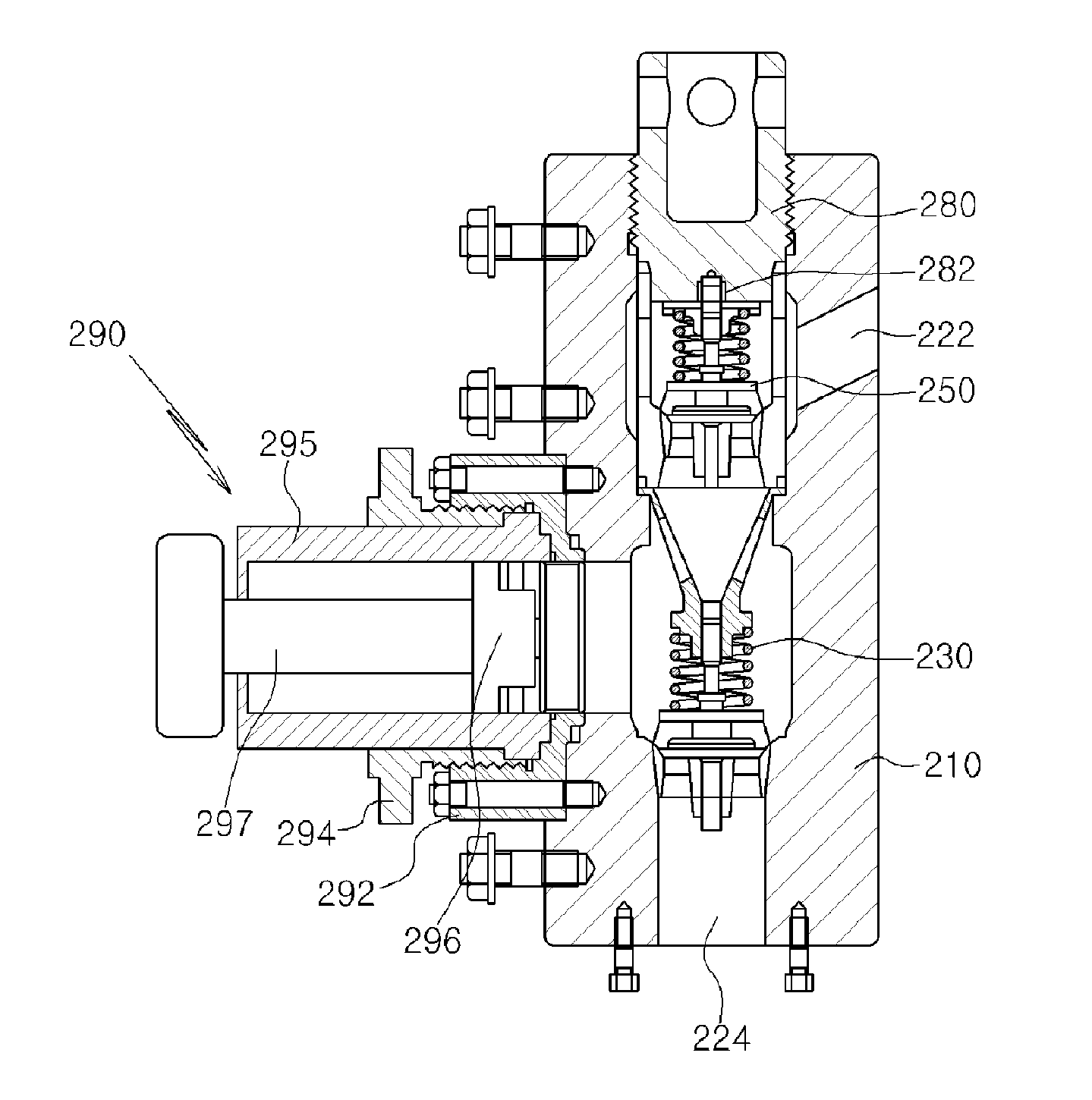
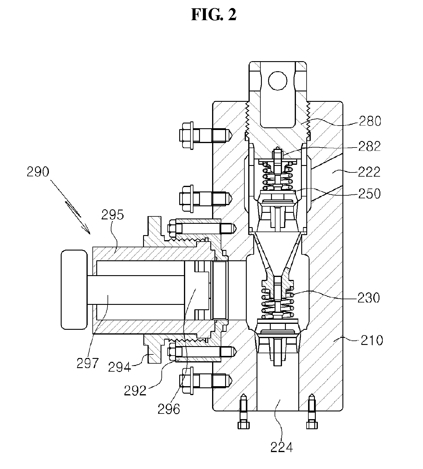
[0030]FIG. 2 is a sectional view showing a sludge suction apparatus according to the exemplary embodiment of the present invention, FIG. 3 is a sectional view showing a housing of the sludge suction apparatus according to the exemplary embodiment of the present invention, FIG. 4 is a half-sectional view showing an exhaust valve of the sludge suction apparatus according to the exemplary embodiment of the present invention, and FIG. 5 is a half-sectional view showing a suction valve of the sludge suction apparatus according to the exemplary embodiment of the present invention.

[0031]As shown in the drawings, the slu...


PUM


Abstract

Disclosed is a sludge suction apparatus for an offshore structure. The sludge suction apparatus includes a housing having an upper mounting hole and a lower mounting hole; a suction valve installed in the lower mounting hole in line with a suction hole to selectively suck sludge according to variation of internal pressure of the housing; an exhaust valve installed in the upper mounting hole to communicate with the exhaust hole and aligned coaxially with the suction valve to exhaust the sludge to an outside through the exhaust hole;a valve port coupled to an upper portion of the upper mounting hole and formed with a fixing groove coupled with an upper portion of the exhaust valve; and a piston assembly fixedly coupled with the coupling section and reciprocated in forward and rearward directions to operate the suction valve and the exhaust valve.

Description

BACKGROUND OF THE INVENTION[0001]1.Field of the Invention[0002]The present invention relates to a sludge suction apparatus for an offshore structure. More particularly, the present invention relates to a sludge suction apparatus for an offshore structure, in which the sludge suction apparatus has no suction valve fixing unit, so that the manufacturing cost thereof can be reduced, and the sludge suction apparatus is easily assembled and disassembled so that stability and workability can be improved and operation efficiency thereof can be enhanced.[0003]2. Description of the Related Art[0004]In general, a sludge suction apparatus for an offshore structure is used in the chemical industrial field, the construction industrial field and the offshore plant field to supply a great amount of sludge or mud under high pressure for a long period of time. The sludge suction apparatus is very expensive, so the maintenance and repair work must be frequently performed with respect to the sludge su...

Claims


Application Information

Patent Timeline
Patent Type & Authority Applications(United States)
IPC IPC(8): F04B15/02F04B53/10F04B39/10
CPCF04B53/102F04B15/02Y10T137/7938
Inventor KIM, YOUNG-JUKIM, DEOK HWANCHUNG, SO KEULWOO, NAM-SUB
Owner KOREA INST OF GEOSCI & MINERAL RESOURCES
Why Eureka
Try Eureka