Subtalar arthroereisis implant apparatus and treatment method

a technology of subtalar arthroereisis and implant apparatus, which is applied in the field of treatment of excessive pronation of feet, can solve the problems of immense force, large error space, and high cost of devices and modifications, and achieve the effects of maximum, success, comfort and performan

Active Publication Date: 2011-08-25
FELDMAN KENT A
View PDF10 Cites 19 Cited by
  • Summary
  • Abstract
  • Description
  • Claims
  • Application Information

AI Technical Summary

Benefits of technology

[0020]An additional object of this invention is the provision of such a prosthesis which is surface-customized, using a three-dimensional weight-bearing image of the patient, and means to form an exterior surface of the implant, which in three dimensions substantially mirrors and / or mates with the individual patient's anatomical area of the sinus tarsi while weight-bearing, thereby providing a substantially perfect fit therein, and allowing the implant to determine the proper positioning of the bones of the patient.
[0022]Yet another object of this invention, is the provision of an implant which will substantially remove the guess work of the medical professional in the operating room, as to the proper final positioning of the patient's bones relative to each other, to secure them in the proper position for weight bearing.
[0026]Currently, a horizontally disposed CAT scanner is employed, to capture a three-dimensional image of a patient's foot, after the foot has been placed in the proper posture, and while the patient bears weight on the foot. The employment of 3D imaging to capture the dimensional characteristics of the bones of the patient's properly positioned weight bearing foot, thereby yields an implant adapted to engage and hold the foot in the proper position.

Problems solved by technology

Symptoms frequently include pain, weakness, fatigue, and throbbing or cramping discomfort.
Such devices and modifications can be very expensive, especially in younger patients who frequently outgrow them and require replacements.
However, most such devices are of a one-design-fits-all configuration and leave a vast majority of the size, shape, and engagement position to what can best be described as the surgeon or medical professional's experienced estimate.
With size, engagement method, positioning, angling, and a host of other factors to consider, there is considerable room for error.
Further, because these threaded or screwed or similar elongated implants employ a permanent mechanical engagement with the bones involved, at a very small space on the circumference of the implant, there is an immense amount of force imparted to each respectively engaged bone on the very small surface area of engagement with the implant.
This small area of engagement, and due to a mismatch in the chosen implant shape, and the sinus tarsi anatomy, there are abnormal impact stresses applied to the bones.
Such stress is a common cause in treated patients of post-arthroereisis pain which is generally one of the major factors patient's choose such implants in the first place.
While this mechanical engagement and one-design-fits-all concept works well in mechanical components, in the human body, employing a hard metallic member of a singular shape or configuration, and implanting it through mechanical engagement in a biologically diverse population of patients all having infinitely variable bone and joint positioning aspects, is less than ideal.
Further, when deciding at what position to position the foot bones of the patient, to employ the implant to hold that position, it is again a professional educated guess, since the implant does not determine the ultimate position of the engaged bones.
Consequently, the medical professional must use x rays and professional estimates of what is needed and how it should be engaged which can be less than accurate and fail to product optimum patient outcomes.

Method used


Image

  • Subtalar arthroereisis implant apparatus and treatment method
  • Subtalar arthroereisis implant apparatus and treatment method
  • Subtalar arthroereisis implant apparatus and treatment method

Examples


Embodiment Construction

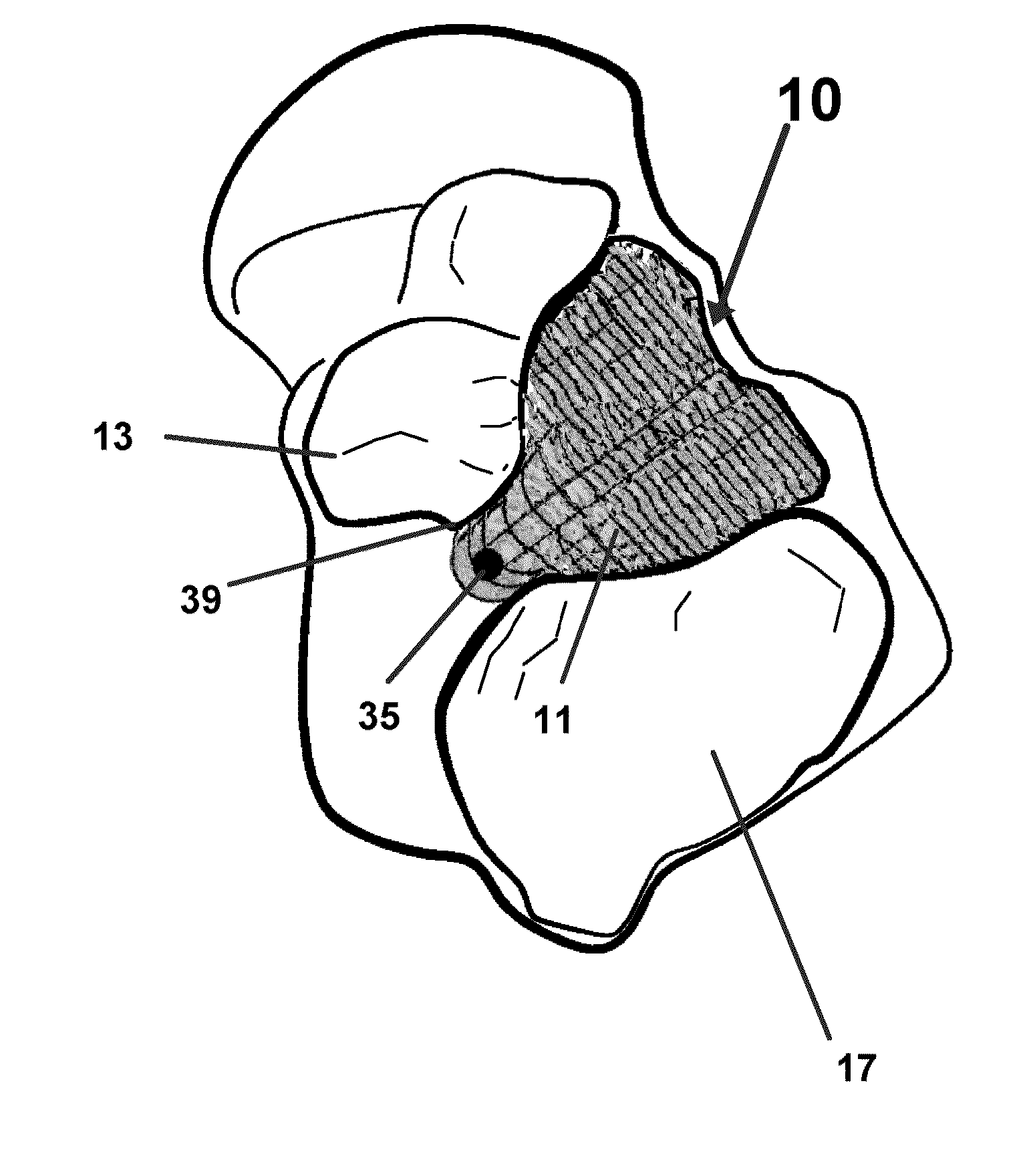
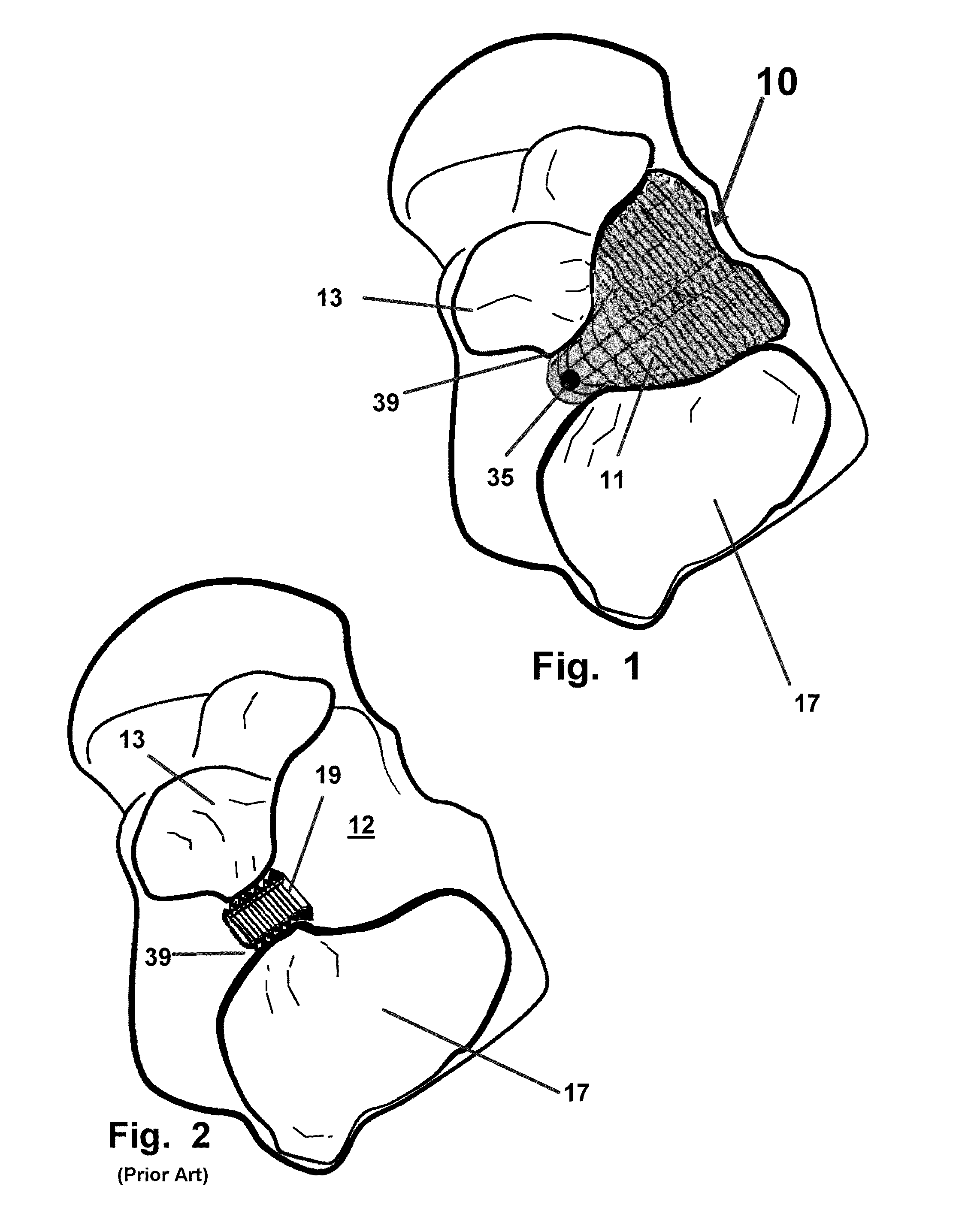
[0054]Referring now to the drawings 1-4, where similar components and structures are denoted with like numerals, there is seen in FIG. 1 an illustration of the device 10 herein formed by the disclosed method for the device 10. As depicted in the horizontal sliced view through the anatomic space of the sinus tarsi 12, the device 10 is engaged therein and has been formed with the proper topography and resulting sides and surfacing to maximize contact of the device 10 surfaces 11 with the adjacent bone structures of the middle calcaneal facet 13 and the shown posterior facet 17. The surfaces 11 so formed, yield a device whose dimensions and exterior surfaces 11 which substantially mirror the topography of the surrounding anatomic space of the sinus tarsi 12.

[0055]So implanted, the device 10 provides a means to substantially maintain the relative positions of the bones engaged with the sides 11 of the device, to maintain the patient's foot in a substantially proper posture or position f...


PUM


Abstract

A device and method of manufacturing and implanting a custom subtalar arthroereisis implant having side surfaces which are mirrored in topography with the sinus tarsi of a patient. The implant is formed using images of the patient standing in a weight bearing position with their sinus tarsi and the surrounding bone structure in an anatomically correct alignment. Once implanted, the implant urges and maintains the anatomically correct alignment thereby minimizing any patient tendency for abnormal motion between said patent's talus and calcaneus.

Description

[0001]This application claims priority to U.S. Provisional Application 61 / 307,723, filed on Feb. 24, 2010, and incorporated herein in its entirety by reference hereto.FIELD OF THE INVENTION[0002]The disclosed device and method relate to the treatment of excessively pronated feet, more commonly known as flat feet. More particularly the device and method herein, relates to the patient-individualized design and manufacture of a surgical subtalar arthroereisis implant configured for treatment of patients with excessively pronated feet. The implant is designed and thereafter formed based upon electronic imaging of a patient's foot while weight-bearing. Digital image files are thereafter employed to form a virtual computer-assisted three dimensional design and subsequent construction of an implant configured for the specific anatomy of each individual patient.BACKGROUND OF THE INVENTION[0003]In human anatomy, the subtalar joint, also known as the talocalcaneal joint, provides for the arti...

Claims


Application Information

Patent Timeline
Patent Type & Authority Applications(United States)
IPC IPC(8): A61F2/42
CPCA61F2/4202A61F2002/30579A61F2002/3071A61F2002/4223A61F2002/3095A61F2002/30952A61F2002/30948
Inventor FELDMAN, KENT A.
Owner FELDMAN KENT A
Why Eureka
Try Eureka