Display method and electronic device for using the same

Inactive Publication Date: 2011-08-25
HTC CORP
View PDF12 Cites 18 Cited by
  • Summary
  • Abstract
  • Description
  • Claims
  • Application Information

AI Technical Summary

Benefits of technology

[0006]Accordingly, the present invention provides a display meth

Problems solved by technology

In other words, with the increasing variety of functions of the electronic devices, it is not easy for the user to target the page of content or the tab as quickly as the user wants.
Also, it is not easy for th

Method used


Image

  • Display method and electronic device for using the same
  • Display method and electronic device for using the same
  • Display method and electronic device for using the same

Examples


Embodiment Construction

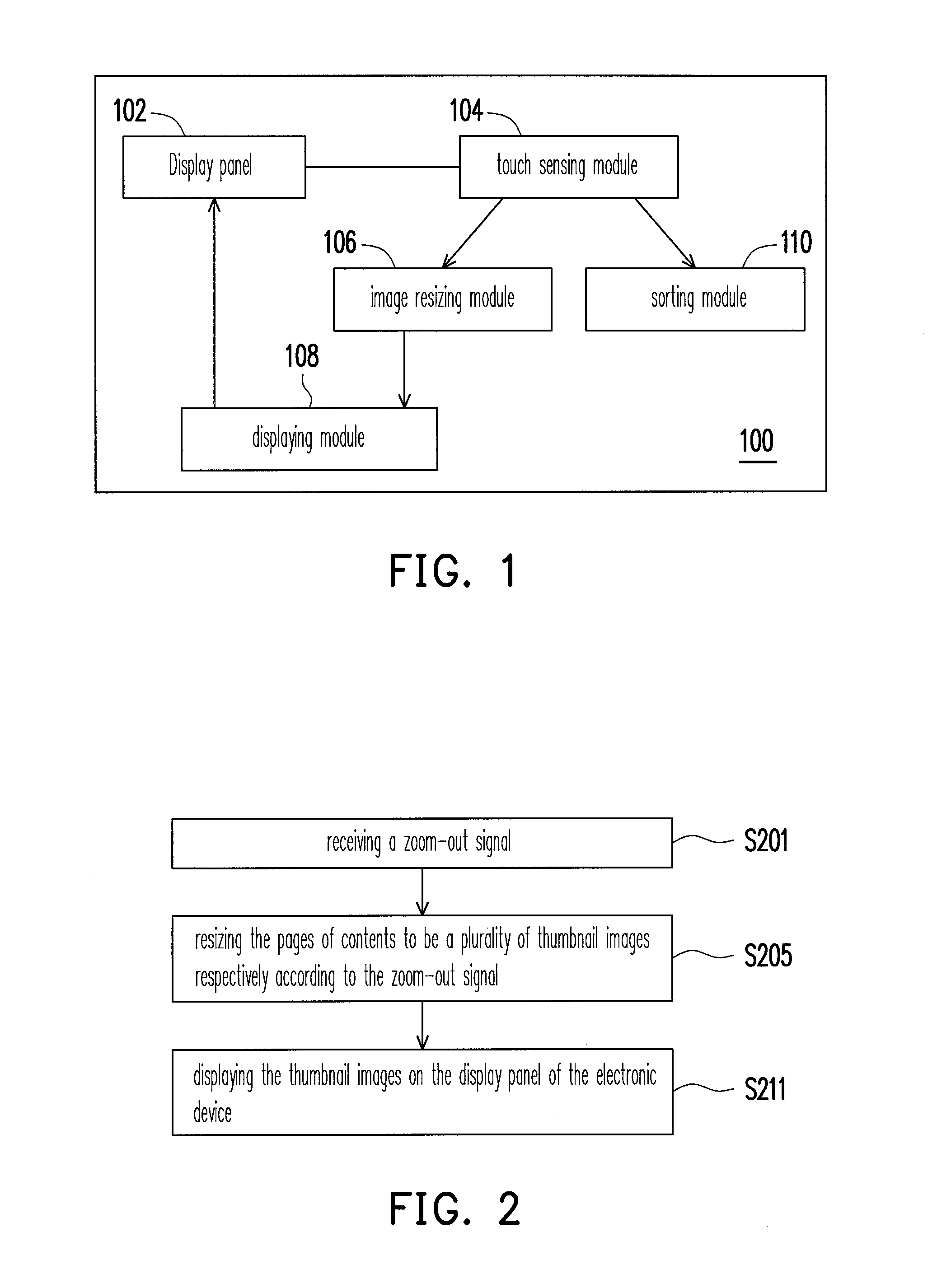
[0044]FIG. 1 is a block diagram schematically showing an electronic device according to one embodiment of the invention. As shown in FIG. 1, an electronic device 100 of the present embodiment comprises a display panel 102, a touch sensing module 104, an image resizing module 106 and a displaying module 108. Further, the electronic device 100 can also comprises a sorting module 110. The electronic device 100 can be, for example but not limited to, a personal computer (PC), a mobile phone, a smart phone, a personal digital assistant, a palmtop play station (such as PSP / GBA), a MP4 / PMP player, a digital camera, a tablet PC, or a notebook computer, and the scope thereof is not limited herein. It should be noticed that the display panel 102 can be integrated with the touch sensing module 104 to be a touch panel.

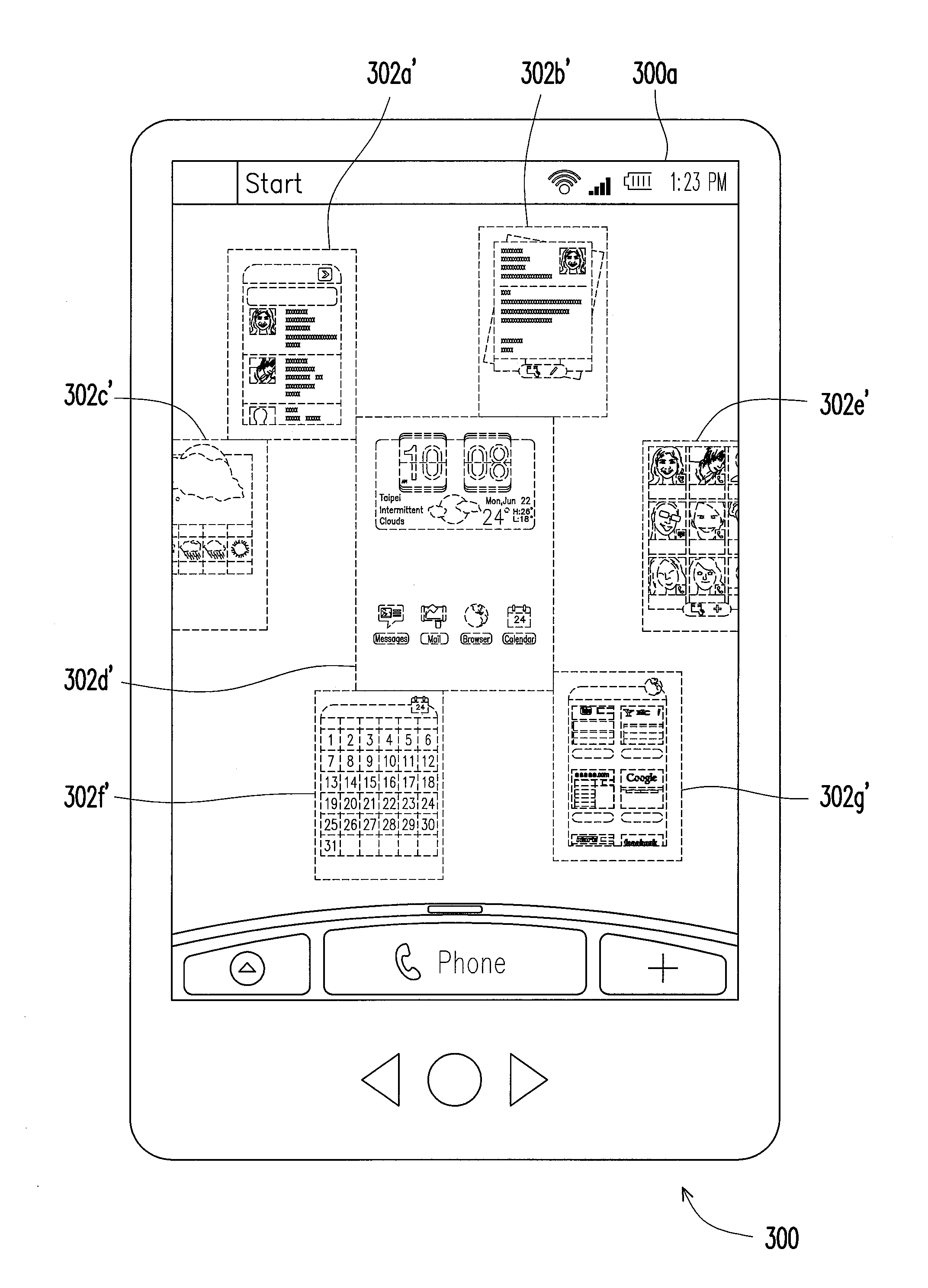
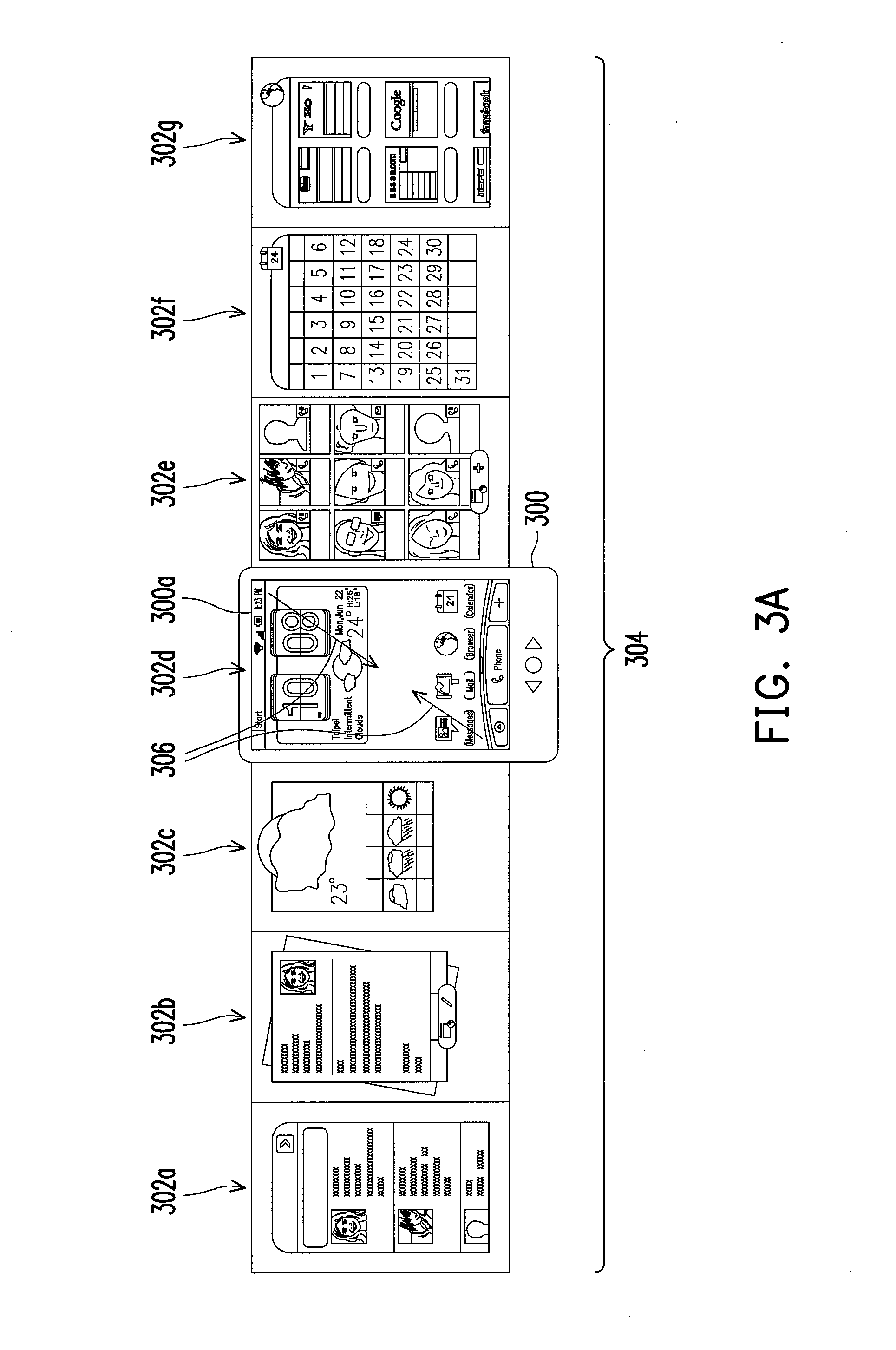
[0045]FIG. 2 is a flow chart showing a display method for an electronic device according to one embodiment of the invention. FIGS. 3A through 3D are schematic views showing the dy...


PUM


Abstract

The invention provides a display method for an electronic device. The electronic device has a display panel displaying at least one of a plurality of pages of contents and the pages of contents are contiguously arranged in a page flow. The display method comprising receiving a zoom-out signal and resizing the pages of contents to be a plurality of thumbnail images respectively according to the zoom-out signal and displaying the thumbnail images on the display panel of the electronic device.

Description

BACKGROUND OF THE INVENTION[0001]1. Field of Invention[0002]The present invention relates to an operating method and an electronic device for using the same. More particularly, the present invention relates to a display method and an electronic device for using the same.[0003]2. Description of Related Art[0004]With the advancement of the portable electronic devices, the functionalities of the portable electronic device are various. The portable electronic devices such as the mobile phone, the personal digital assistant (PDA) or digital camera, sometimes, possess multiple functions. For instance, the mobile phone or the PDA not only provides the simple telecommunication function but also supports the short message transmission and receiving functions while the user is not available for answering the incoming calls immediately. Besides, the portable electronic device can further stores and plays multimedia files and provide the user an editable calendar for recording miscellaneous not...

Claims


Application Information

Patent Timeline
IPC IPC(8): G06F3/048G06F3/033
CPCG06F3/0483G06F3/0485G06F2203/04806G06F15/0283G06F3/04883
Inventor BAMFORD, DREWBRINDA, DAVIDCIELAK, MATTHEW JOSEPHHUANG, SHENG-HSIN
Owner HTC CORP
Why Eureka
Try Eureka