Modernization method for elevator installations

a technology for modernizing methods and elevators, applied in the direction of elevators, manufacturing tools, other domestic objects, etc., can solve the problems of increasing the risk of hydraulic fluid escape, and affecting so as to improve the safety of the elevator installation, the effect of increasing the spacing

Active Publication Date: 2011-09-01
INVENTIO AG
View PDF2 Cites 5 Cited by
  • Summary
  • Abstract
  • Description
  • Claims
  • Application Information

AI Technical Summary

Benefits of technology

[0008]Moreover, it is advantageous that the support means is fixed by its first end in the region of the drive unit and is led around the support roller, which lies below the fixing point, of the counterweight, is subsequently led around the drive pulley of the drive unit disposed at the top, led downwardly to the first car support roller and deflected by 90° around this, led horizontally below the elevator car along the underside and deflected upwardly at the second car support roller through 90° and finally led to a further fixing point present in the upper region of the elevator shaft. This method step, which can also be carried out in reverse sequence, has the advantage that a secure mounting is made possible, wherein the space required is optimized with respect to the previously existing hydraulic drive. The modernization method is thereby suitable for a large number of hydraulically actuated elevator installations of different design.
[0009]In advantageous manner a drive platform is mounted on the elevator car below this, wherein the drive platform has the car support rollers or the car support rollers are connected with the elevator car by means of the drive platform. The drive platform enables reliable mounting of the existing elevator car, wherein modifications of the existing elevator car are not required or required to only a small extent. The drive platform can in that case consist substantially of a continuous beam in which the car support rollers are incorporated or are attached thereto. The continuous beam is preferably substantially narrower than a depth of the elevator car. The beam is flange-mounted from below on the existing elevator car, wherein it replaces an equivalent beam of the former elevator, by way of which the elevator car was supported on the piston rod of the hydraulic cylinder. The stability of shape of the existing elevator car is in that case utilized in advantageous manner, particularly if the entire structure is guided at elevator guide rails by way of guide shoes mounted on the elevator car and is stabilized in three-dimensions. The lower guide shoes can, however, also be present at the newly mounted drive platform so as to achieve a greater degree of spacing between the upper and lower guide shoes and thus improved travel characteristics of the elevator car.
[0010]In addition, the drive platform can advantageously provide different functions which are not realized or only partly realized in the existing hydraulic elevator installation. For example, the drive platform can comprise a load measuring device by way of which the elevator car is supported on the drive platform so that the instantaneous load and thus the loading of the elevator car can be ascertained. In addition, the drive platform can comprise a safety device which is designed as catch equipment (safety brake device) and / or operating brake device. Thus, further functions which, in particular, improve the safety of the elevator installation can be integrated in the elevator installation during modernization.
[0011]Moreover, it is advantageous if a drive platform is provided which comprises a main beam with two end parts displaceable and lockable relative to this main beam, wherein the car support rollers are mounted in or at these end parts. This enables adaptation to elevator cars of different design or having different widths as also to differences in the arrangement of the support means, whereby a greater range of use results. Such an adjustability, which serves for adaptation to different car widths, etc., of the drive platform can be of advantage, but is not absolutely necessary.

Problems solved by technology

However, hydraulic elevators have a relatively high energy consumption and need for maintenance and are always susceptible to the risk of escape of hydraulic fluid, which must not pass into the groundwater.
The modernization method known from DE 101 54 171 A1 has the disadvantage that the possibility of use is limited.
A significant disadvantage of the known modernization method also resides in the fact that the drive arrangement thereof requires a substantial spacing between the ceiling of the elevator shaft and the roof of the elevator car.

Method used


Image

  • Modernization method for elevator installations
  • Modernization method for elevator installations
  • Modernization method for elevator installations

Examples


Embodiment Construction

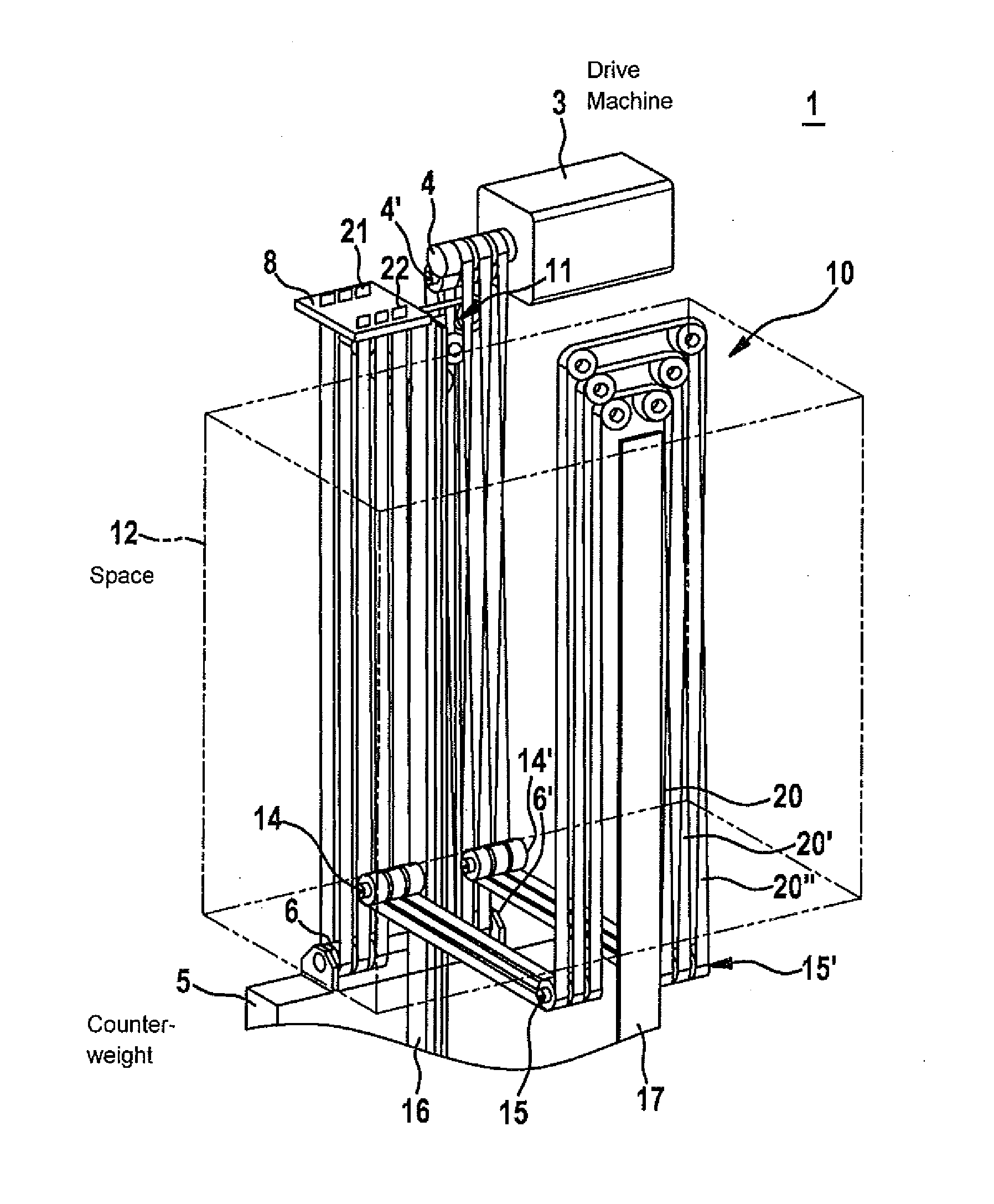
[0020]FIG. 1 shows a first possible form of embodiment of an elevator installation 1 in a schematic illustration, which has been converted by a modernization method in correspondence with a first exemplifying embodiment of the invention. The modernization method in that case starts from a hydraulically actuated elevator installation. This hydraulically actuated elevator installation is converted by means of the modernization method into an elevator installation 1 driven by a drive machine with a drive pulley. Components, which are no longer needed, of the existing hydraulically actuated elevator installation can be removed within the scope of the conversion. Individual components, even if these are no longer used, can in a given case also remain in the elevator installation. However, essential elements of the hydraulically actuated elevator installation are taken over in the modernization method of the invention, so that the costs of the modernization are limited. Essentially change...


PUM

PropertyMeasurementUnit
movementaaaaaaaaaa
operating timeaaaaaaaaaa
energy consumptionaaaaaaaaaa

Abstract

A modernization method for converting a hydraulically actuated elevator system into an elevator system driven by a drive machine having a drive sheave makes it possible to convert and retain some essential elements of the existing elevator system. Car support rollers are arranged beneath an underside of an elevator car in the area of points of the underside of the elevator car located opposite each other and are connected to the elevator car. Furthermore, a support is guided along the underside of the elevator car and about the car support rollers. The support is also guided about the drive sheave so that the support can be driven by the drive sheave of the drive machine in order to raise and lower the elevator car.

Description

FIELD OF THE INVENTION[0001]The invention relates to a modernization method for conversion of a hydraulically actuated elevator installation into an elevator installation, which is driven by a drive machine with a drive pulley, and to modernized elevator installation, which is produced by such a method. In particular, the invention relates to the field of modernization of hydraulically actuated elevator installations which for reasons of environmental protection are not to continue in operation and are to be replaced by drive pulley elevators.BACKGROUND OF THE INVENTION[0002]A method of converting a hydraulic elevator, which is arranged in an elevator shaft, into a drive cable-pulley elevator is known from DE 101 54 171 A1. The known method for modernization relates to hydraulic elevator installations which were, in particular, erected in large numbers in the 1960s and 1970s, since a reliable and relatively economic possibility was made available by these for equipping buildings—eve...

Claims


Application Information

Patent Timeline
Patent Type & Authority Applications(United States)
IPC IPC(8): B23P6/00
CPCB66B19/007B66B19/002B66B19/005Y10T29/4973B66B11/0206Y10T29/49716Y10T29/49721B66B19/02
Inventor FISCHER, DANIEL
Owner INVENTIO AG
Why Eureka
Try Eureka