Portable, non-lethal, self defense device with disabling mechanism

Inactive Publication Date: 2011-09-01
DAPPER CHARLES P
View PDF12 Cites 27 Cited by
  • Summary
  • Abstract
  • Description
  • Claims
  • Application Information

AI Technical Summary

Benefits of technology

[0019]In the preferred embodiment, the top flap is snap fit into the cylindrical bore. Although snap fit is the preferred embodiment, due to its simplicity, the hinge pin could also be spring loaded to automatically move the top flap downward to the stop after the top flap has been lifted to access the actuator. This spring will also allow the top flap to be forcefully engaged with the stop preventing accidental depression of the actuator when the device is placed into a users pocket, bag, purse, or other enclosed article.
[0020]In a further embodiment the top flap is communication with a gate adjacent to the aperture of the front wall, wherein manipulation of the top flap will move the gate. An upwards movement of

Problems solved by technology

U.S. Pat. No. 5,310,086 shows a canister holder for an aerosol device that is disarmed when the canister support is removed from the canister holder, but the canister support is only removable in one direction and does not provide a mechanism to adjust the removal tension.
U.S. Pat. No. 5,531,359 shows a housing for holding an aerosol canister that includes a rem

Method used


Image

  • Portable, non-lethal, self defense device with disabling mechanism
  • Portable, non-lethal, self defense device with disabling mechanism
  • Portable, non-lethal, self defense device with disabling mechanism

Examples


Embodiment Construction

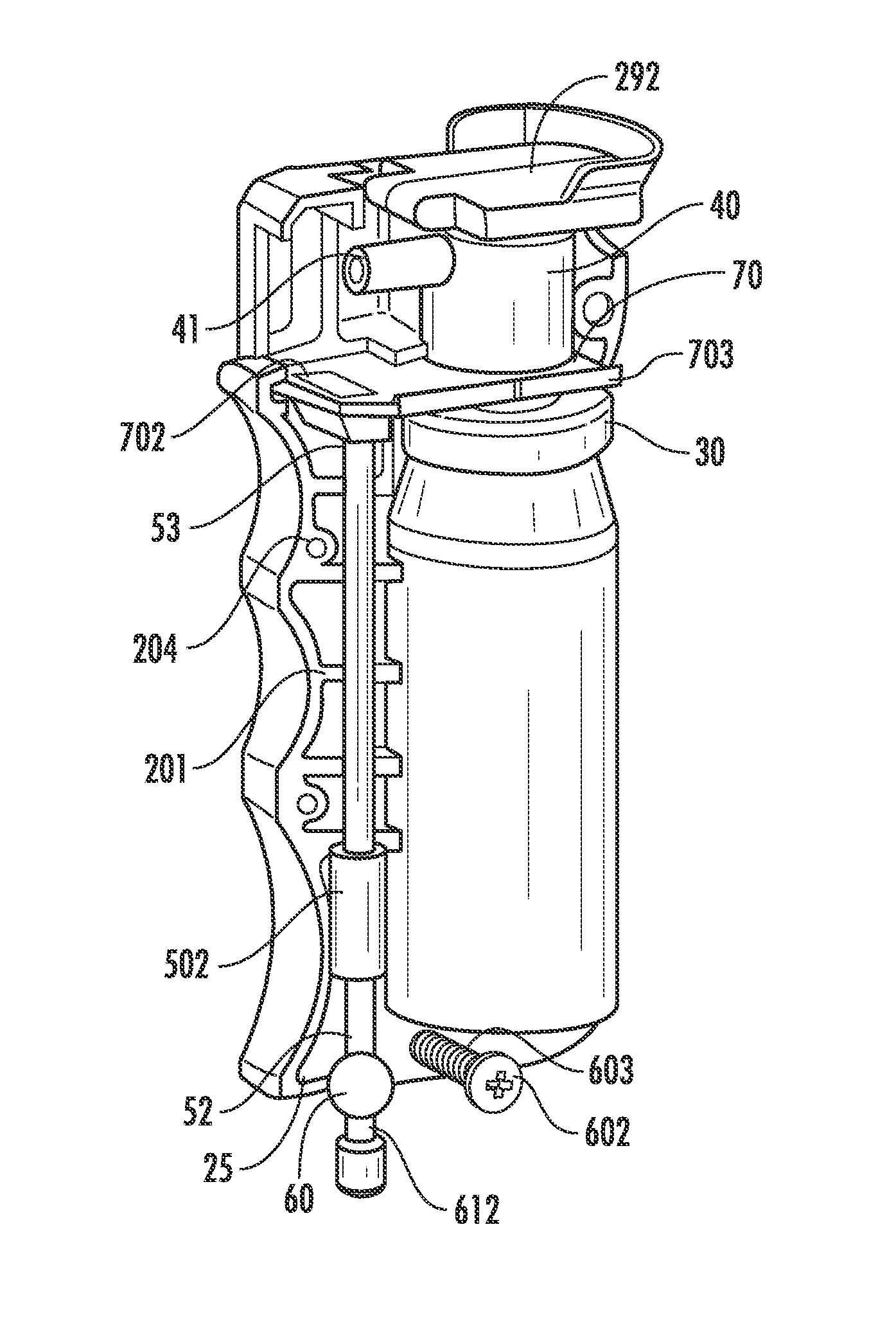
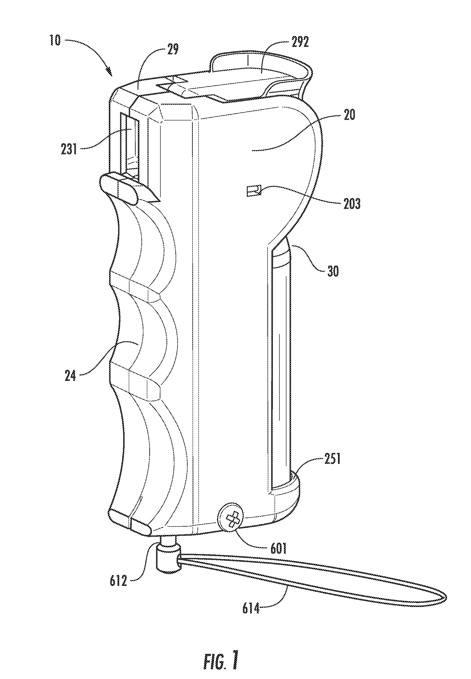
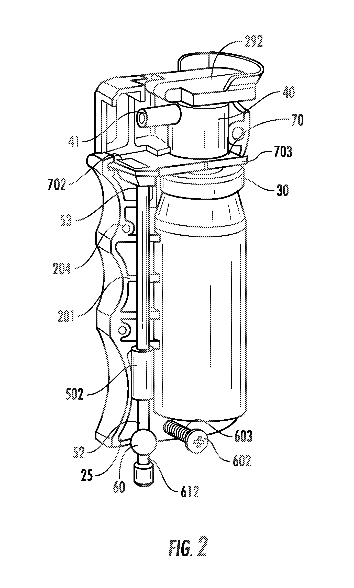
[0030]Referring now to FIGS. 1-4 there is shown an embodiment of the self defense device of the present invention, generally designated by the reference numeral 10. Housing 20 comprises a front canister assembly support structure 21 and rear canister assembly support structure 22, which structures securely attach a canister assembly 30 within the housing. Canister assembly 30 is not completely encapsulated within the housing 20 with a majority of its body length and sidewalls being visible and located outside housing 20. Canister assembly 30, for example, contains an aerosolized propellant with an irritant, and comprises a valve and hollow valve stem 31. The valve stem 31 is movable relative to the canister between an extended closed position and compressed open position in which propellant is free to leave the canister.

[0031]An actuator 40 is disposed on the valve stem 31 and includes a nozzle 41. Actuator 40 has a through orifice 42 adapted to establish open communication between ...


PUM


Abstract

A personal self defense device containing a housing, grip section, canister, actuator, a slide plate, and disarming device. The disarming device prevents operation of the device should the device be removed from the grasp of a victim. The disarming device can rotate in several directions and the force required for its operation can be adjusted. The device further includes a camera, illumination device, power source, and memory storage device.

Description

CROSS REFERENCE TO RELATED APPLICATIONS[0001]This application claims the benefit of provisional patent application Ser. No. 61 / 308,808, filed 2010 Feb. 25 by the present inventor.FEDERALLY SPONSORED RESEARCH[0002]Not ApplicableSEQUENCE LISTING OR PROGRAM[0003]Not ApplicableFIELD OF THE INVENTION[0004]The present invention relates to a non-lethal self defense device that uses a chemical spray to disable a potential attacker.BACKGROUND OF THE INVENTION[0005]Since the beginnings of time, individuals have felt the need to defend themselves from others who might be attempting to harm them. Often a potential victim is forced to either submit to the attacker or try and defend themselves. While defending themselves an individual may use a weapon or security device to gain an advantage over a potential attacker, if they happen to be carrying a self defense device at the time of the attack. Ideally, this device will be non-lethal allowing the potential victim to escape from harm without perma...

Claims


Application Information

Patent Timeline
IPC IPC(8): F41H9/10B65D83/22B65D83/38
CPCF41H9/10
Inventor DAPPER, CHARLES P.
Owner DAPPER CHARLES P
Why Eureka
Try Eureka