Method and device for output of granulate from the bottom of a tank that in addition to granulate holds liquid

Active Publication Date: 2011-09-01
UVAN HLDG
View PDF16 Cites 6 Cited by
  • Summary
  • Abstract
  • Description
  • Claims
  • Application Information

AI Technical Summary

Benefits of technology

[0013]The inlet for pressurized gas also includes a ring-shaped chamber that surrounds the periphery of the tubular ejector and is connected with the inside of the ejector through a ring-shaped slit that directs the pressurized gas

Problems solved by technology

Even though the method and device described in U.S. Pat. No. 4,294,784 have proven to be successful, it may occur under certain operational circ

Method used


Image

  • Method and device for output of granulate from the bottom of a tank that in addition to granulate holds liquid
  • Method and device for output of granulate from the bottom of a tank that in addition to granulate holds liquid
  • Method and device for output of granulate from the bottom of a tank that in addition to granulate holds liquid

Examples


Embodiment Construction

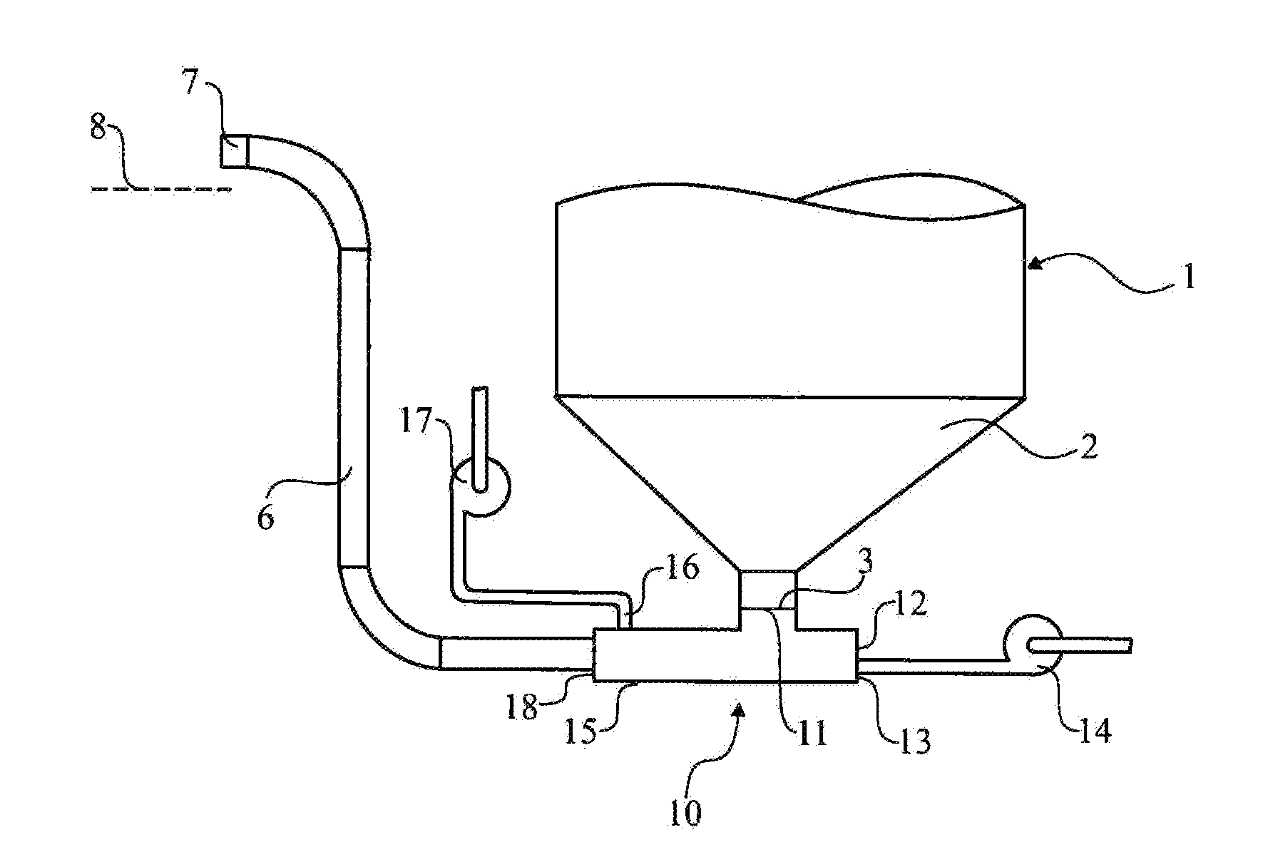
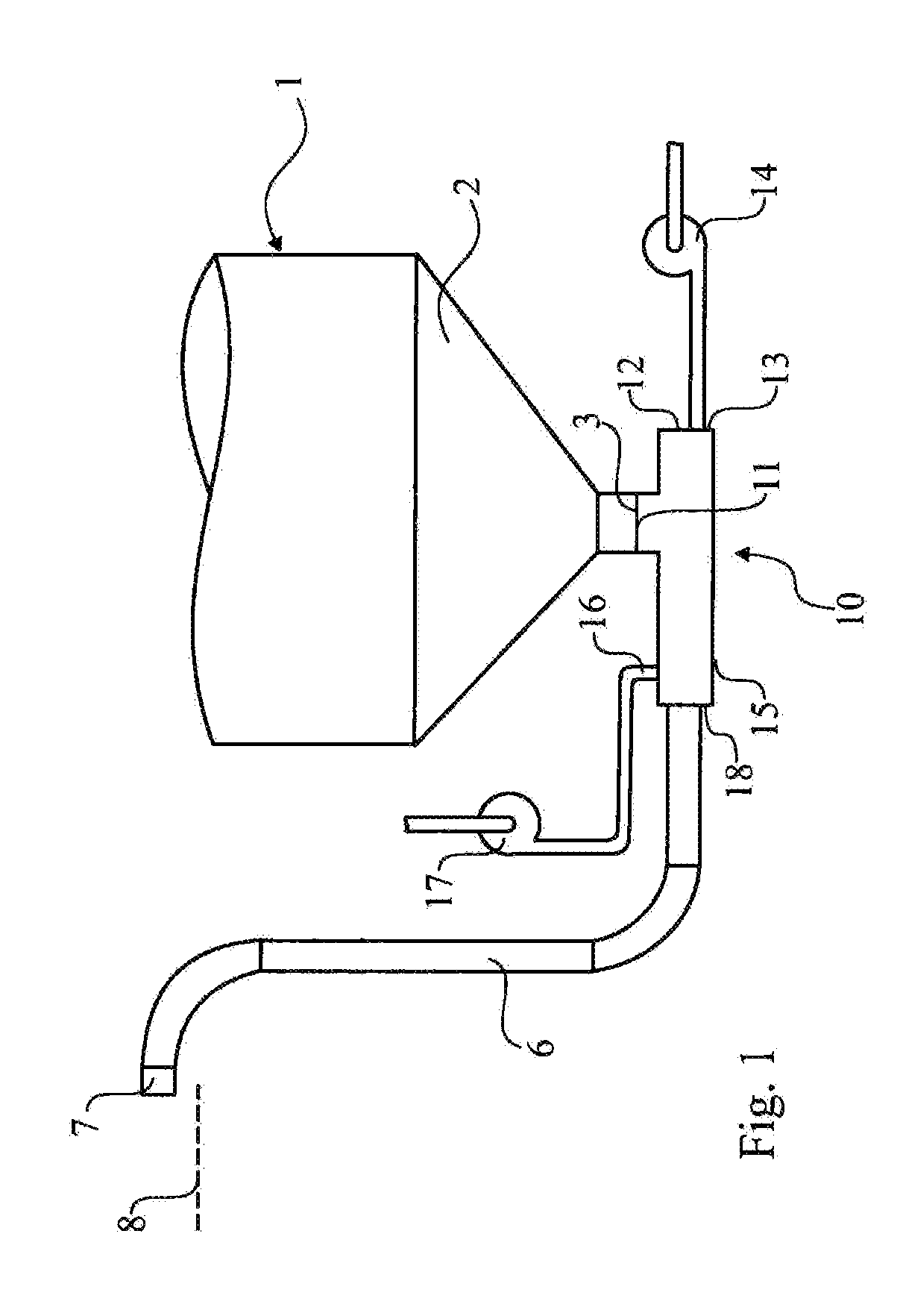
[0018]FIG. 1 shows a device for output of granulate from a tank 1. Granulate of metals or metal alloys is produced in a known way in that a jet (not shown) of molten metal or alloy is allowed to hit a fireproof impact element (not shown) and be scattered into drops that fall into the tank 1 that contains cooling water so that they are quickly cooled. The tank has a narrowing conical bottom 2 with an outlet 3 for mixing granulate and used cooling water. New cooling water is supplied at another place by means of a conduit (not shown) and excess cooling water is generally supplied so that there is also an overflow for conducting away used cooling water. After quick cooling a mixture of the granulate formed and water from the outlet 3 is conducted through a conduit system 6, 7 with air supply for formation of a three-phase flow and farther up to a separation surface 8, for example a vibrating sieve, that is located at a higher level than the outlet 3, where the water can run off from th...


PUM

PropertyMeasurementUnit
Angleaaaaaaaaaa
Accelerationaaaaaaaaaa
Transport propertiesaaaaaaaaaa

Abstract

For transport of granulate from a granulation tank by means of liquid and air, an ejector is provided with a side inlet for granulate, a first end with a spray nozzle for pressurized transport liquid, and a second end with an inlet for pressurized gas. Downstream from the second end, an outlet spray nozzle for a three-phase flow of liquid, granulate, and gas is provided. A first conduit has a lower end connected with the outlet for transport of the three-phase flow. The ejector includes a tubular ejector housing with an internal wear liner and an outlet spray nozzle made from a durable material. The inlet for pressurized gas includes a ring-shaped chamber that surrounds the periphery of the ejector and is connected with the inside of the ejector through a ring-shaped slit that directs the pressurized gas towards the outlet of the ejector.

Description

TECHNICAL AREA[0001]The current invention concerns a method and a device for output of granulate from the bottom of a tank that in addition to granulate holds liquid.STATE OF THE ART[0002]Granulates of metals and metal alloys are manufactured in that a jet of molten metal or alloy may hit an impact element and be scattered into drops that fall into a liquid tank having a narrowing conical bottom so that they quickly cool. A successful method and device is described in U.S. Pat. No. 4,294,784. In order to avoid the granulate sintering together into larger aggregates, the granulate is moved out of the cool water tank as soon as the drops have congealed after cooling, after which the water can run off and the granulate can dry due to its own inherent heat. The heated cooling water is used for transport, which runs out of the tank by itself at the lowest point in the bottom and brings with it the congealed granulate through a bend and up through an inclined riser to a separation surface...

Claims


Application Information

Patent Timeline
IPC IPC(8): B05B7/14
CPCB22F2009/0832B22F2009/0896B22F2998/00B65G53/14B65G53/42B65G53/30B22F9/082B65G2812/1641B65G2812/1625B65G2201/042B22F9/08F04F5/00
Inventor LUNDSTROM, CHRISTOFFERFOLGERO, KARE
Owner UVAN HLDG
Why Eureka
Try Eureka