Multiplexing readout scheme for a gamma ray detector

Active Publication Date: 2011-09-01
GENERAL ELECTRIC CO
View PDF4 Cites 55 Cited by
  • Summary
  • Abstract
  • Description
  • Claims
  • Application Information

AI Technical Summary

Benefits of technology

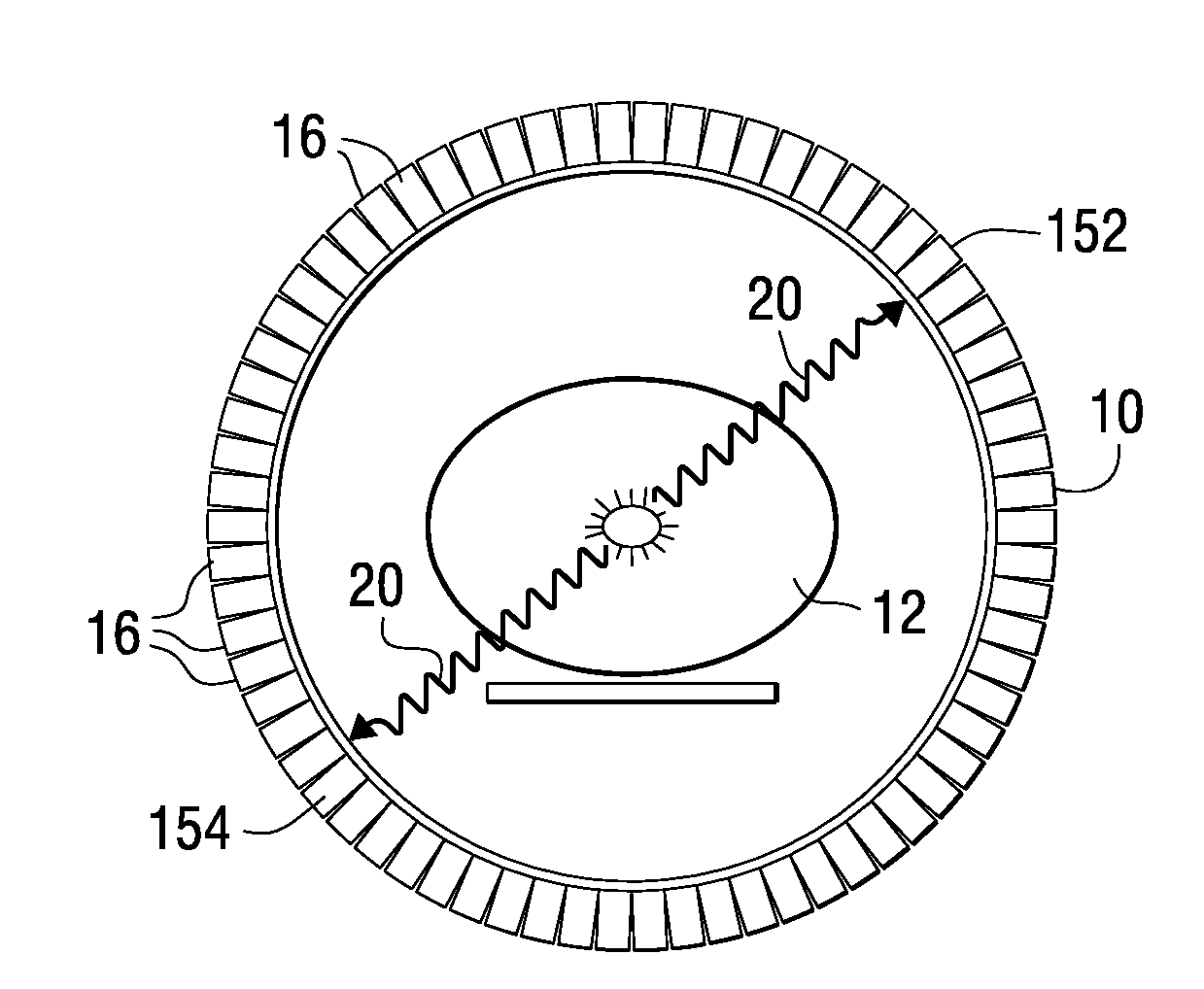
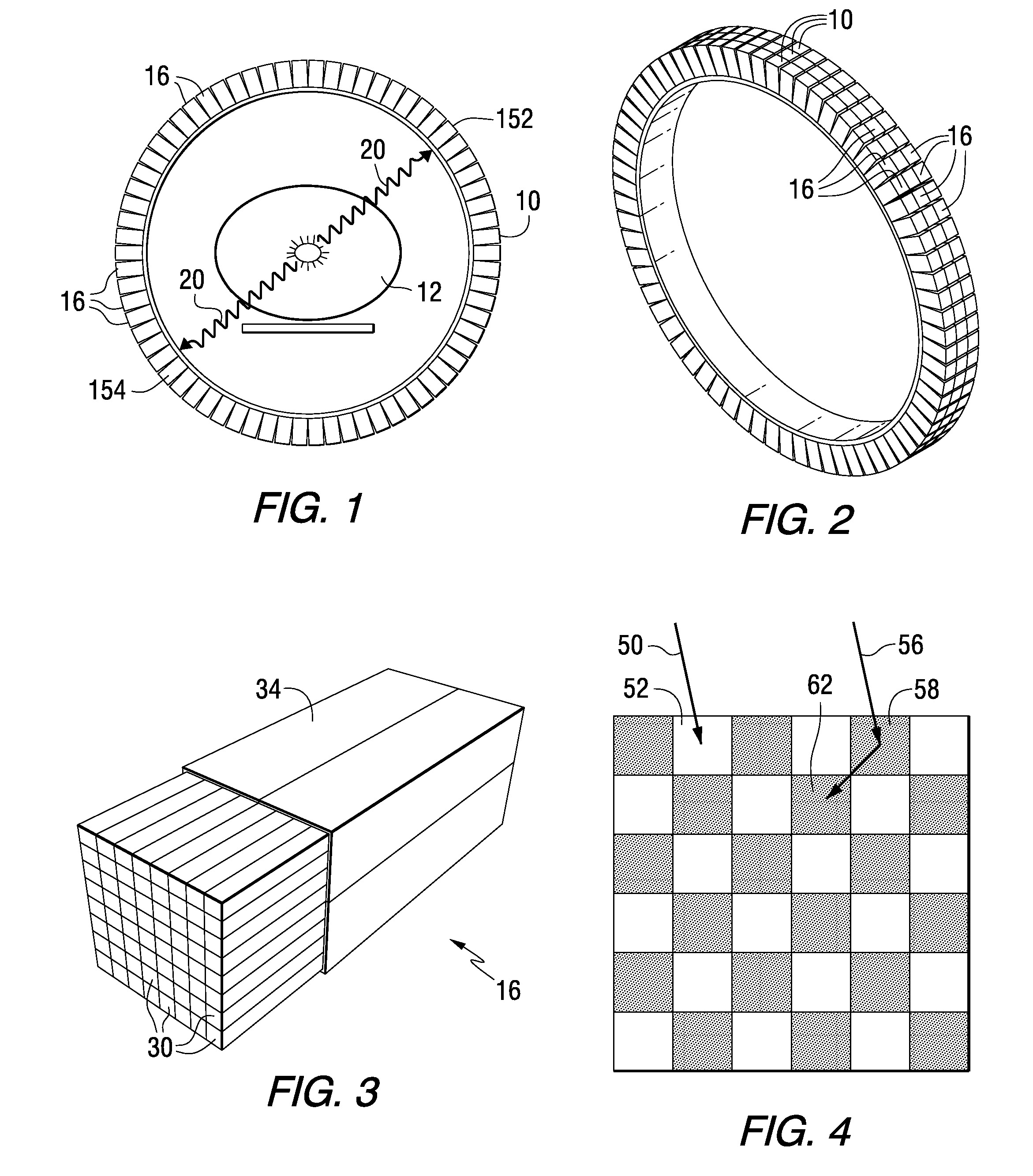
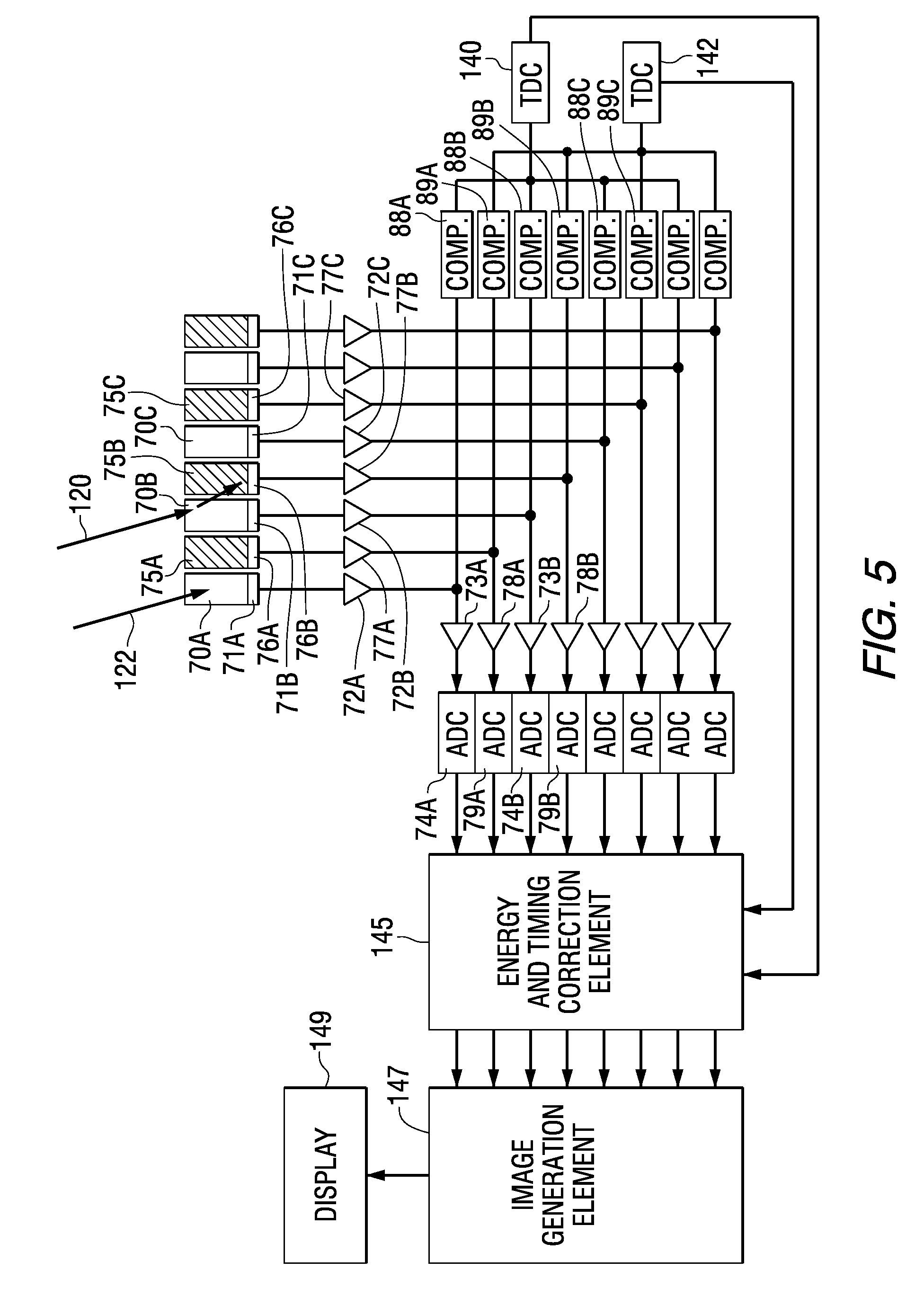
[0026]One embodiment of the invention comprises a method for producing a PET image of a tissue using a PET scanner, the scanner comprising a plurality of scintillation crystals and a plurality of detectors. The method comprises forming a first crystal group including a first subset of the plurality of crystals; forming a second crystal group including a second subset of the plurality of crystals, wherein crystals comprising the first crystal group are different from crystals comprising the second crystal group; converting a first beam striking one or more crystals of the first crystal group to a first electrical signal; converting a second beam striking one or more crystals of the second crystal group to a second electrical

Problems solved by technology

A one-to-one coupling of the crystals and the PMTs is not possible due to a thickness of the PMT glass.
Further, manufacture of a one-to-one coupling block detector is expensive.
If the resolving time of the detectors is greater than about 1 ns, it is difficult to localize the origin of the gamma rays to a segment of the LOR.
The additional SSPMs and the one-to-one coupling with the crystals provide considerably improved timing and spatial resolution, but also create problems due to the requirement for higher density in the processing electronics components, resulting in the dissipation of additional power

Method used


Image

  • Multiplexing readout scheme for a gamma ray detector
  • Multiplexing readout scheme for a gamma ray detector
  • Multiplexing readout scheme for a gamma ray detector

Examples


Embodiment Construction

[0037]Before describing in detail the particular method and apparatus related to PET scanner readout schemes, it should be observed that the present invention resides primarily in a novel and non-obvious combination of elements and process steps. So as not to obscure the disclosure with details that will be readily apparent to those skilled in the art, certain conventional elements and steps have been presented with lesser detail, while the drawings and the specification describe in greater detail other elements and steps pertinent to understanding the inventions.

[0038]The presented embodiments are not intended to define limits as to the structures, elements or methods of the inventions, but only to provide exemplary constructions. The embodiments are permissive rather than mandatory and illustrative rather than exhaustive.

[0039]As described above, to improve the timing and spatial resolution of a time-of-flight detector, it is preferable to couple one scintillation crystal to one s...


PUM


Abstract

A method for producing a PET image of a tissue using a PET scanner, the scanner comprising a plurality of scintillation crystals (70X/75X) and a plurality of detectors (71X/76X). The method comprises forming a first crystal group (160X) including a first subset of the plurality of crystals; forming a second crystal group (164X) including a second subset of the plurality of crystals, wherein crystals comprising the first crystal group (160X) are different from crystals comprising the second crystal group (164X); converting a first beam (120) striking one or more crystals of the first crystal group (70X/160X) to a first electrical signal (94); converting a second beam striking one or more crystals of the second crystal group (75X/164X) to a second electrical signal (98), wherein the second beam is scattered from the first beam; determining one or both of a first and a second timing relationship, wherein the first timing relationship (Δt2) is a time interval between a value of the first electrical signal (94) and a time reference (t1), and the second timing relationship (Δt3) is a time interval between a value of the second electrical signal (98) and the time reference (t1); correcting the second electrical signal (98) to produce a corrected second electrical signal using a correction factor derived from at least one of the first and the second timing relationships to compensate for energy in the second signal scattered from the first signal; and creating an image of the tissue (12) using the corrected second electrical signal.

Description

FIELD OF THE INVENTION[0001]This invention relates generally to gamma ray detection and in particular to an apparatus and method for correcting for gamma ray scattering in a detector, the correction accomplished using a multiplexing readout scheme.BACKGROUND OF THE INVENTION[0002]Gamma ray detectors are used in several different applications, including in a positron emission tomography (PET) apparatus. PET is a nuclear medicine imaging technique that produces a three-dimensional image or picture of functional processes within a body. The system detects pairs of gamma rays that are emitted indirectly by a positron-emitting radionuclide (tracer) that is introduced into the body on a biologically active molecule. Images of the tracer concentration in 3-dimensional space within the body are reconstructed by computer analysis. In modern scanners, this reconstruction is often accomplished with the aid of a CT x-ray scan performed on the patient during the same session and using the same a...

Claims


Application Information

Patent Timeline
IPC IPC(8): G01T1/20
CPCA61B6/037G01T1/2985
Inventor KIM, CHANG LYONGMCDANIEL, DAVIDHEUKENSFELDT JANSEN, FLORIBERTUS P.M.
Owner GENERAL ELECTRIC CO
Why Eureka
Try Eureka