Photovoltaic power generation system

a photovoltaic power generation and photovoltaic technology, applied in the direction of dc source parallel operation, transportation and packaging, sustainable buildings, etc., can solve the problems of large number of cables, difficult cable routing, and disadvantageous workability of the structure shown in fig. 19 to avoid waste in the routing of conductors

Inactive Publication Date: 2011-09-01
SHARP KK
View PDF9 Cites 141 Cited by
  • Summary
  • Abstract
  • Description
  • Claims
  • Application Information

AI Technical Summary

Benefits of technology

[0024]According to the structure of the present invention, since the photovoltaic power generation system includes a plurality of connection cables to which the units are each connected such that the units are parallelly connected to each other, it is possible to avoid waste in the routing of conductors and the like in parallelly connecting the plurality of units, and furthermore, since a failure detection section that performs failure detection and outputs a detection result on a unit-by-unit basis is provided, failure detection can be performed with respect to the units on a unit-by-unit basis.

Problems solved by technology

However, with the structure shown in FIG. 19, since the number of the high-voltage-output solar cell modules M102 in the parallel connection is large, the distance between the junction box JB102 and a string located far away from the junction box JB102 is so long that it is difficult to route a cable, and furthermore, a large number of cables are required.
This makes the structure shown in FIG. 19 disadvantageous in terms of workability.

Method used


Image

  • Photovoltaic power generation system
  • Photovoltaic power generation system
  • Photovoltaic power generation system

Examples


Embodiment Construction

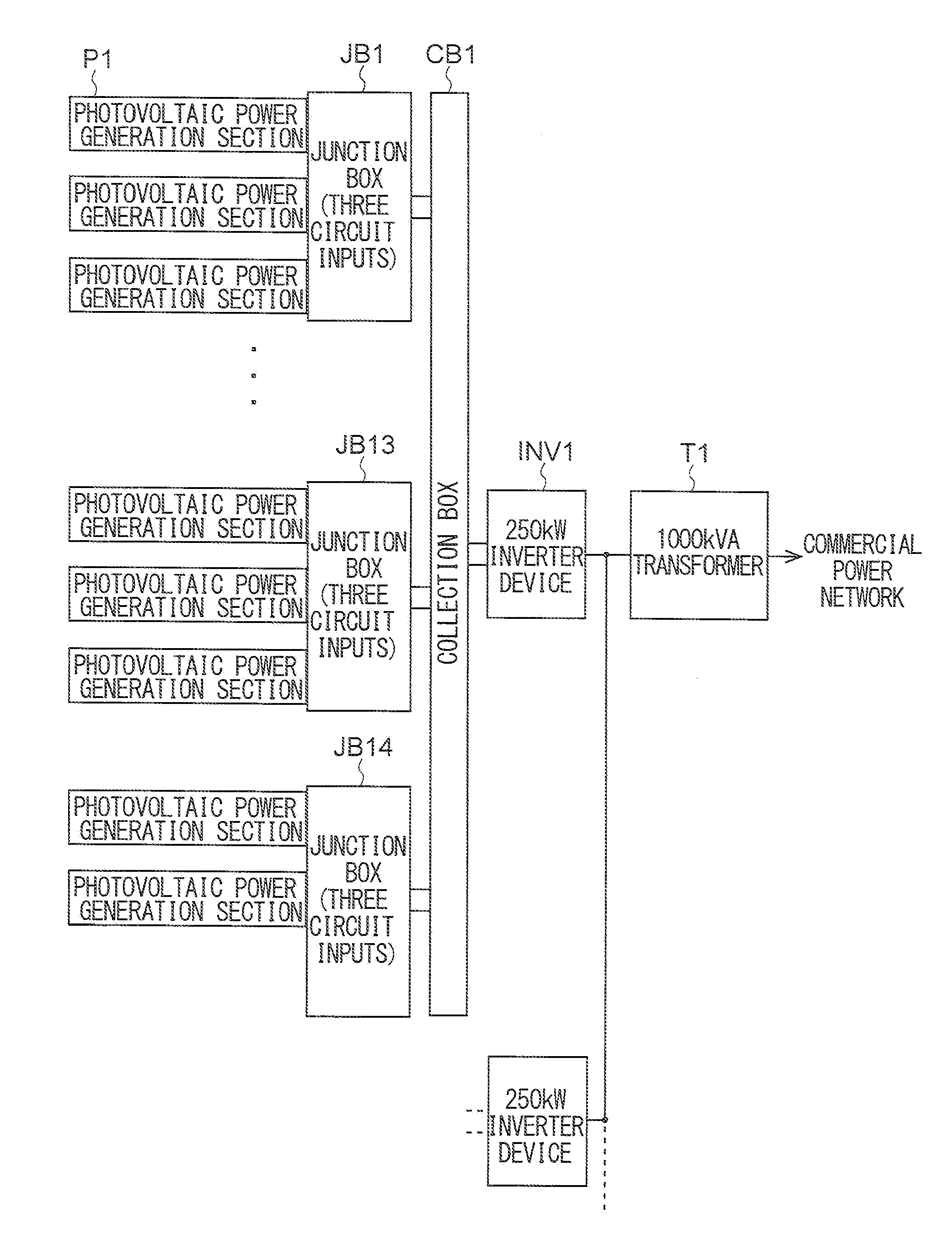
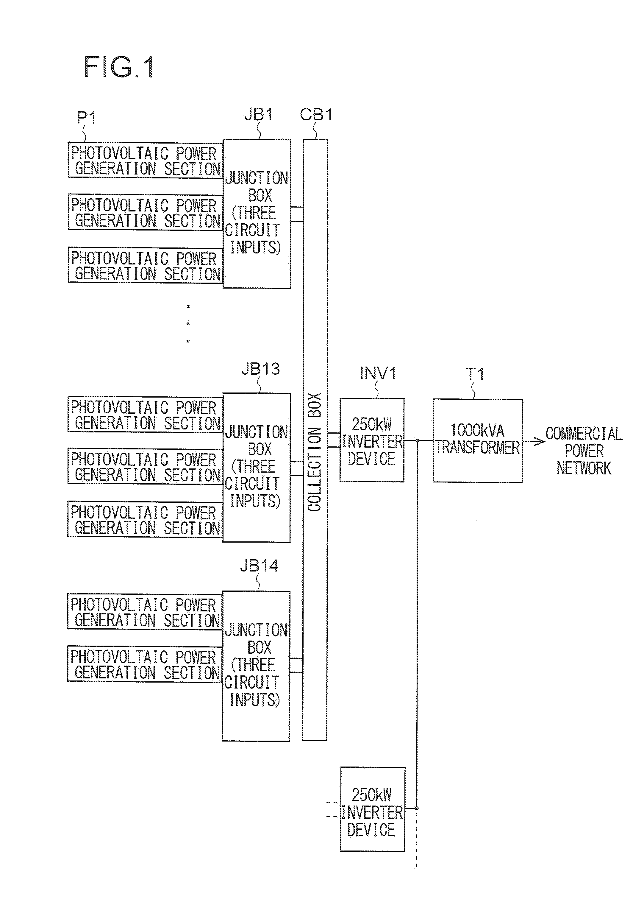
[0046]Hereinafter, a description will be given of an embodiment of the present invention with reference to the drawings. An example of the overall structure of a photovoltaic power generation system according to the present invention is shown in FIG. 1. The photovoltaic power generation system shown in FIG. 1 is an industrial photovoltaic power generation system of 10 kW or more, and the system includes a plurality of blocks each including: junction boxes JB1 to JB13 each having three circuit inputs and each having three photovoltaic power generation sections P1 connected thereto; a junction box JB14 having three circuit inputs and having two photovoltaic power generation sections P1 connected thereto; a collection box CB1 having 14 circuit inputs and having the junction boxes JB1 to JB14 connected thereto; and an inverter device INV1 that has a maximum output of 250 kW and converts direct-current power supplied from the collection box CB1 to alternating-current power. The photovolt...


PUM


Abstract

A photovoltaic power generation system includes: a plurality of units, each of the units being formed with a string, which is a series-connection body of a plurality of solar cell modules, or with a solar cell module; a plurality of connection cables to which the units are each connected such that the units are parallelly connected to each other; a junction box to which each end of the plurality of connection cables is connected; and a failure detection section that performs failure detection and outputs a detection result on a unit-by-unit basis, the failure detection section being located outside the junction box.

Description

TECHNICAL FIELD[0001]The present invention is related to a photovoltaic power generation system, and specifically relates to a photovoltaic power generation system capable of detecting a failure.BACKGROUND ART[0002]In a typical photovoltaic power generation system, direct-current power is generated by a solar cell array formed by parallelly connecting a plurality of series-connected bodies (strings) each of which is composed of a plurality of series-connected solar cell modules, the direct current electric power is converted to alternating-current power by, for example, an inverter device, and the alternating-current power is supplied to a commercial power network.[0003]In a photovoltaic power generation system employing a solar cell module providing a low-voltage output (for example, a crystalline silicon solar cell module having an open voltage of on the order of 20 V), an increased number of solar cell modules are series-connected to each other such that the open voltage of a sol...

Claims


Application Information

Patent Timeline
Patent Type & Authority Applications(United States)
IPC IPC(8): H02J1/10
CPCH01L31/02021Y02E10/56Y02B10/14H02H7/20Y02B10/10
Inventor MITSUOKA, HIROFUMIKUROSAWA, MASAMI
Owner SHARP KK
Why Eureka
Try Eureka