
Volume control system, controller, and amplifying apparatus

Inactive Publication Date: 2011-09-01
ONKYO KK
View PDF13 Cites 18 Cited by
  • Summary
  • Abstract
  • Description
  • Claims
  • Application Information

AI Technical Summary

Benefits of technology

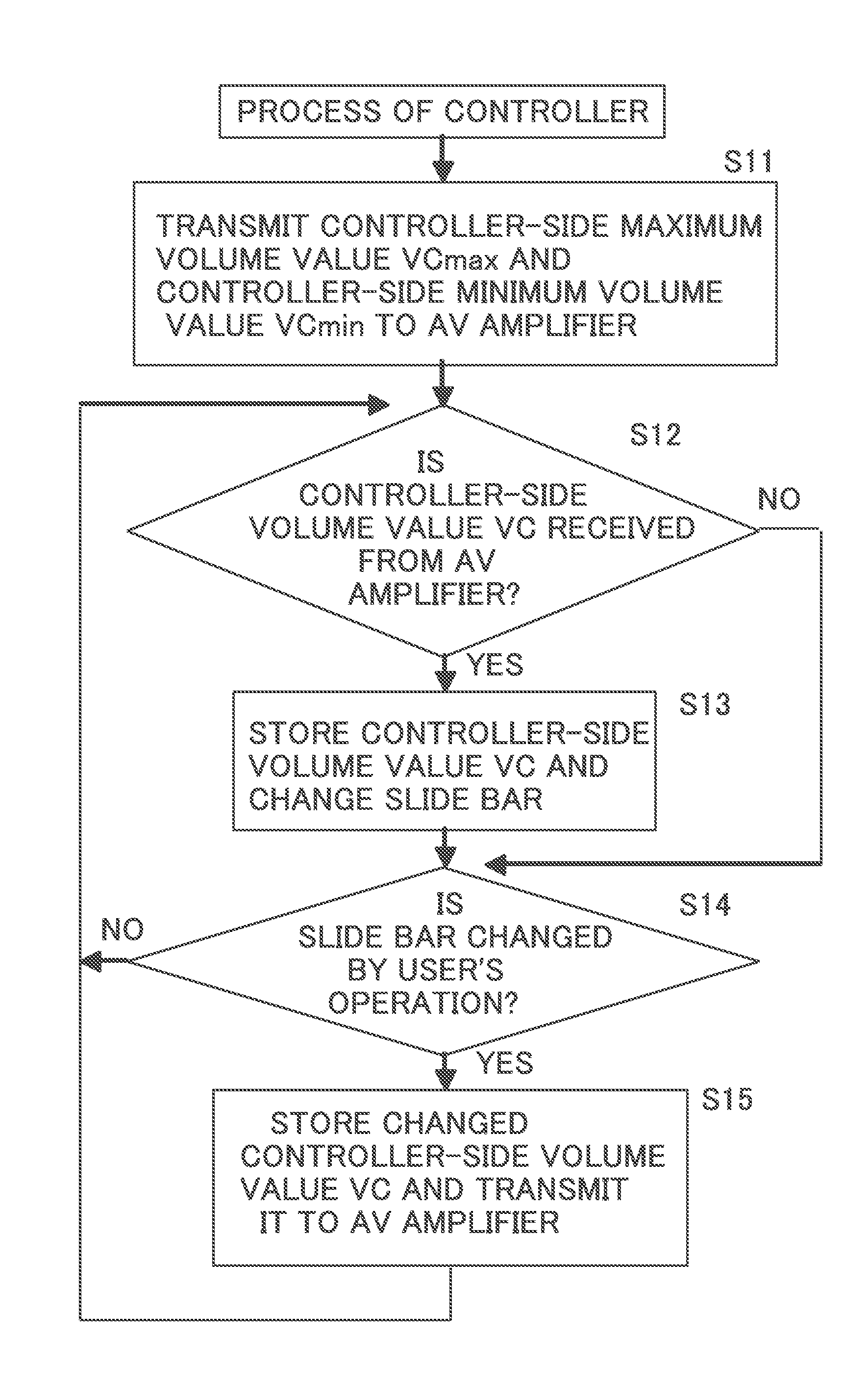
[0008]It is an object of the present invention to provide a volume control system that is capable of suitably changing a volume value of an amplifying apparatus according to a change in a controller-side volume value when the controller-side volume value is changed.
[0013]In this case, even when the controller-side volume value is changed into a controller-side maximum volume value, the amplifier-side volume value does become an amplifier-side maximum volume value or more. For this reason, the amplifier and the speaker can be prevented from being damaged.
[0019]In this case, even when the controller-side volume value is changed into the controller-side maximum volume value, the amplifier-side volume value does not become the amplifier-side maximum volume value or more. For this reason, the amplifier and the speaker can be prevented from being damaged.
[0022]In this case, not the controller-side volume value but the amplifier-side volume value can be input into the controller by a user's operation, the amplifier-side volume value and the controller-side volume value do not have to be converted, and processes of the controller and the amplifier apparatus are simplified. Further, since the controller displays the amplifier-side volume value, the user operates the second input section so that the user can easily understand how much the amplifier-side volume value is changed.
[0025]In this case, not the controller-side volume value but the amplifier-side volume value can be input into the controller by a user's operation. For this reason, the amplifier-side volume value and the controller-side volume value do not have to be converted, and the processes of the controller and the amplifying apparatus are simplified. Further, since the controller displays the amplifier-side volume value, the user operates the second input section and easily understands how much the amplifier-side volume value is changed. Further, since the amplifier-side volume value is not changed into more than an amplifier-side setting maximum volume value by the controller, the amplifier and the speaker can be prevented from being damaged.

Problems solved by technology

As a result, amplifying circuit and speaker of the AV amplifier might be damaged.
However, since the controller cannot recognize the volume value of the AV amplifier, when a user operates a volume knob or a remote controller of the AV amplifier to control the volume value of the AV amplifier, the controller-side volume value set in the controller becomes different from the actual volume value of the AV amplifier.
As a result, the volume of the AV amplifier cannot be suitably changed according to a change in the controller-side volume value.

Method used


Image

  • Volume control system, controller, and amplifying apparatus
  • Volume control system, controller, and amplifying apparatus
  • Volume control system, controller, and amplifying apparatus

Examples


first embodiment

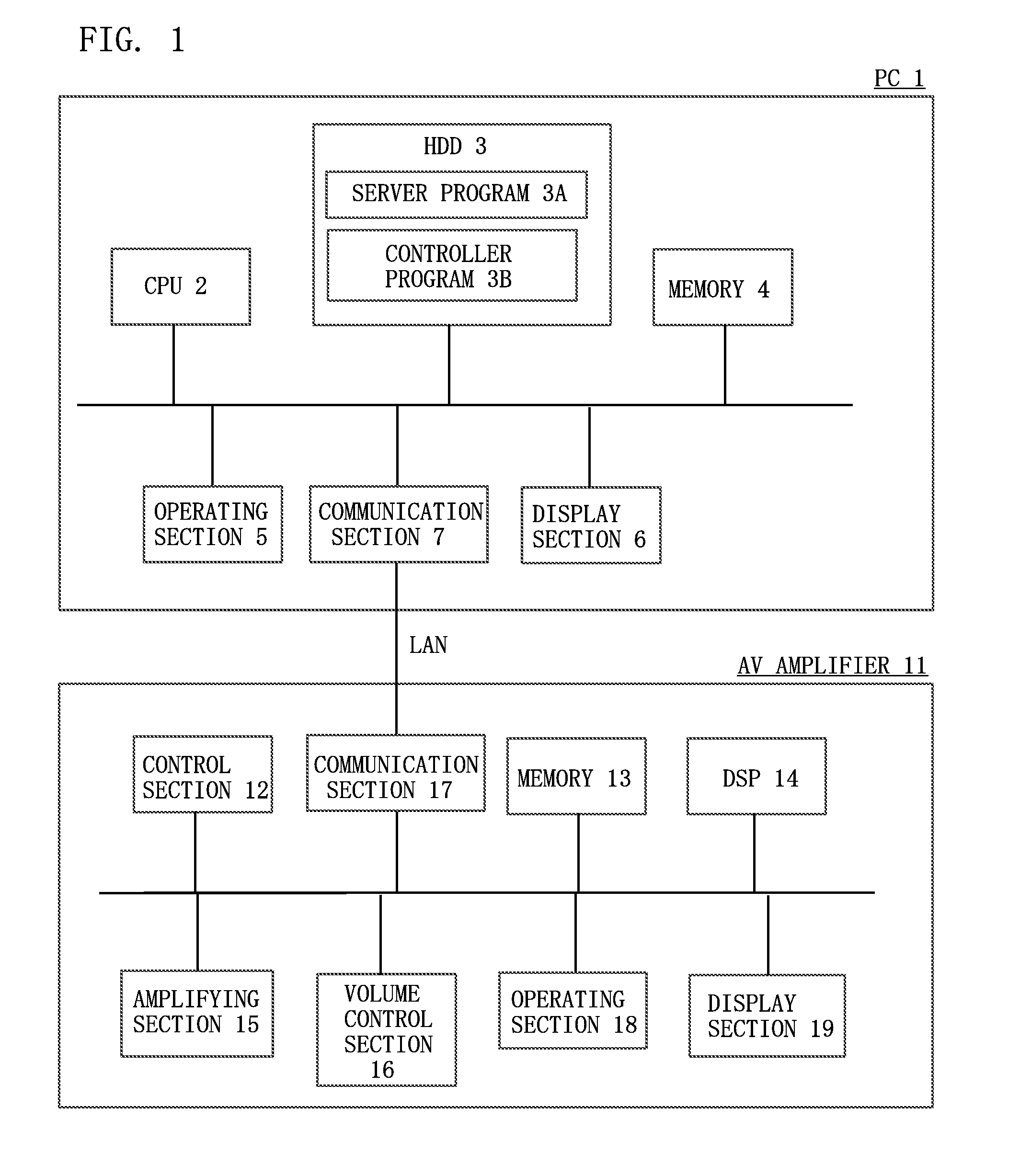
[0079]As shown in FIG. 1, a volume control system of the present invention has a PC 1 and an amplifying apparatus 11 such as an AV amplifier (referred to also as an AV receiver). They can be connected to each other via a network such as LAN. Further, they may be connected to each other via an electric communication line such as HDMI, IEEE394, USB or Internet.

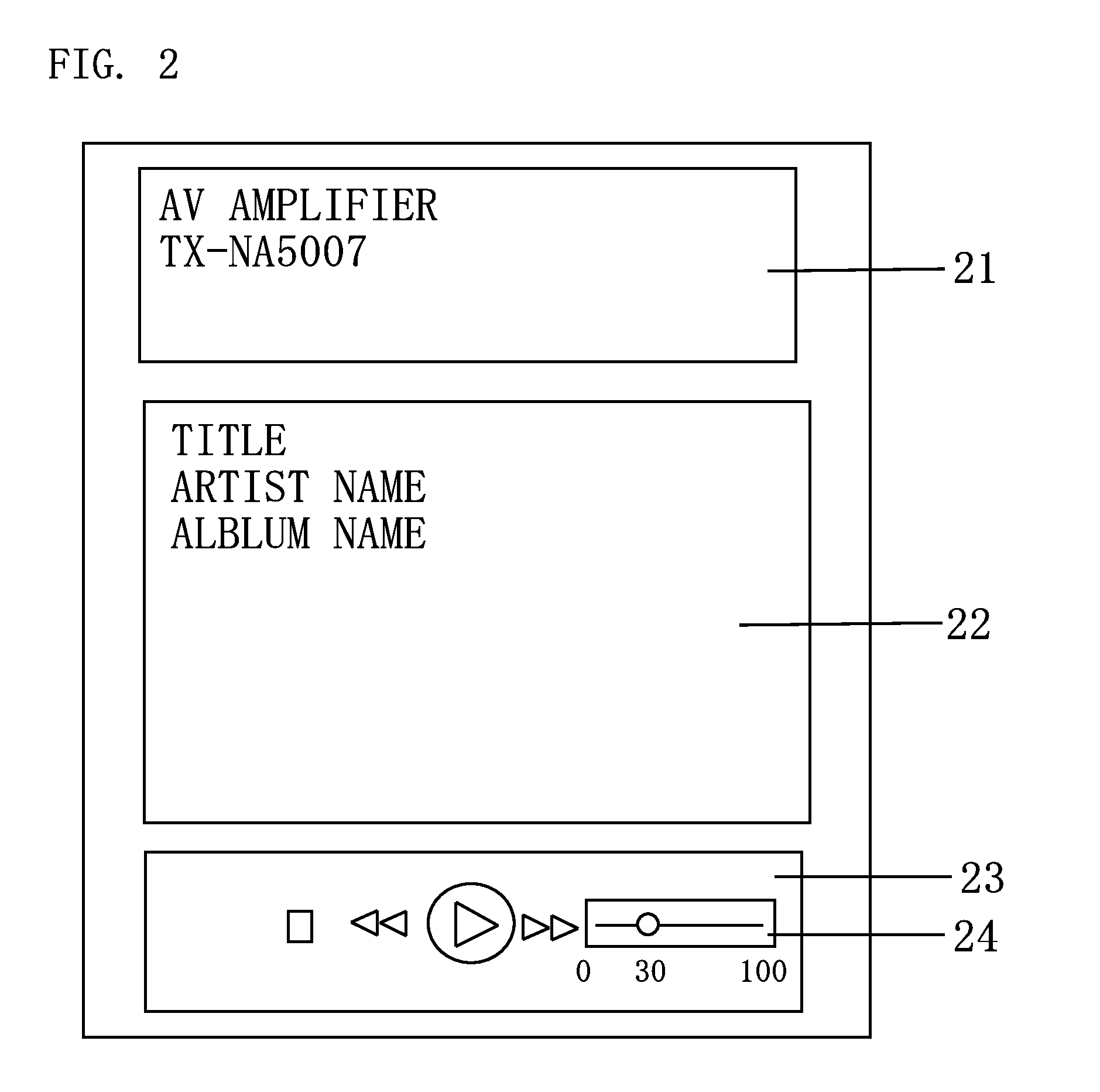
[0080]The PC 1 includes a CPU 2, an HDD 3, a memory (ROM, RAM etc.) 4, an operating section 5, a display section 6, and a communication section 7. The CPU 2 controls the respective sections of the PC 1 based on OS or another program recorded in the HDD 3. The HDD 3 installs a server program (hereinafter, a server) 3A and a controller program (hereinafter, a controller) 3B. These programs are developed in the memory 4 so as to be executed by the CPU 2. A plurality of contents data are recorded in the HDD 3. The contents data are audio data, and in this example, they are audio files. When the server 3A receives a request for trans...

second embodiment

[0097]Another preferred embodiment of the present invention is described below. In comparison with the first embodiment, the controller 3B converts the controller-side volume value VC and the amplifier-side volume value VA in this example. Therefore, the amplifier-side volume value is posted between the controller 3B and the control section 12. FIG. 5 is a flowchart illustrating a process of the control section 12 of the AV amplifier 11, and FIG. 6 is a flowchart illustrating a process of the controller 3B. For example, when the AV amplifier 11 is selected from devices connected to LAN by a user's operation and the controller 3B is connected to the AV amplifier 11, the control section 12 of the AV amplifier 11 reads the amplifier-side maximum volume value VAmax (in this example, 0 dB) and the amplifier-side minimum volume value VAmin (in this example, −50 dB) from the memory 13 and transmits them to the controller 3B (S21) as shown in FIG. 5.

[0098]The controller 3B determines whethe...

third embodiment

[0104]Still another preferred embodiment of the present invention is described below. In comparison with the second embodiment, the controller 3B displays not the controller-side volume value VC (the controller-side maximum volume value VCmax and the controller-side minimum volume value VCmin) but the amplifier-side volume value VA (the amplifier-side maximum volume value VAmax and the amplifier-side minimum volume value VAmin) on the slide bar in this example. FIG. 7 is a flowchart illustrating a process of the controller 3B. The process of the control section 12 of the AV amplifier 11 is the same as that in FIG. 5, and thus the description thereof is employed.

[0105]As shown in FIG. 7, the controller 3B determines whether or not the amplifier-side maximum volume value VAmax and the amplifier-side minimum volume value VAmin are received (S41). When they are received (YES in S41), the controller 3B associates the amplifier-side maximum volume value VAmax with the controller-side maxi...


PUM


Abstract

A volume control system comprises: an amplifying apparatus; and a controller connectable to the amplifying apparatus. The amplifying apparatus includes; a first receiving section for receiving a volume value from the controller, a first input section into which an instruction for changing the volume value is input by a user's operation, a first transmitting section for transmitting the volume value input into the first input section to the controller, and a volume control section for, when the first receiving section receives the volume value or the changed volume value is input into the first input section, controlling a volume value of the amplifying apparatus based on the volume value. The controller includes; a display section for displaying the volume value on a display device, a second receiving section for receiving the volume value from the amplifying apparatus, a changing section for changing the volume value to be displayed on the display device by the display section into the volume value received by the second receiving section; a second input section into which an instruction for changing the volume value to be displayed on the display device by the display section is input by a user's operation; and a second transmitting section for, when the instruction for changing the volume value to be displayed on the display device by the display section is input by the user's operation, transmitting the changed volume value to the amplifying apparatus.

Description

BACKGROUND OF THE INVENTION[0001]1. Field of the Invention[0002]The present invention relates to a volume control system having an amplifying apparatus and a controller.[0003]2. Description of the Related Art[0004]AV amplifier is connected to PC via network such as LAN, and contents reproduction is controlled by control program (hereinafter, controllers) installed into the PC. Server program (hereinafter, servers) is also installed into the PC, and a plurality of audio files are recorded in HDD of the PC. When audio file recorded in the HDD is selected by users' operation, the controller transmits instruction for reproducing the selected audio files to the AV amplifier. The AV amplifier requests the server to transmit the selected audio files. The server reads the selected audio files from the HDD and transmits them to the AV amplifier. The AV amplifier decodes the audio files transmitted from the server, and amplifies them so as to output sounds through speaker.[0005]When instructi...

Claims


Application Information

Patent Timeline
IPC IPC(8): H03G3/00
CPCH03G3/04H03G3/002G06F3/165
Inventor YAMADA, TAKASHIOTSU, KAZUSHIGE
Owner ONKYO KK
Learn More