Eureka AIR delivers breakthrough ideas for toughest innovation challenges, trusted by R&D personnel around the world.

System and method for inspection of stator vanes

a stator valve and inspection system technology, applied in the field of gas turbine engines, can solve the problems of time-consuming and laborious inspection using a borescope, the components of the compressor of the gas turbine engine may wear or develop defects, and the inspection of these components may be difficult to determine wear and/or defects

Active Publication Date: 2011-09-01
GENERAL ELECTRIC CO
View PDF35 Cites 24 Cited by
  • Summary
  • Abstract
  • Description
  • Claims
  • Application Information

AI Technical Summary

Benefits of technology

The patent describes a method and system for recording images of a gas turbine engine's compressor components without needing to remove the housing of the compressor. This allows for easy inspection of any defects in the components. The system includes an image recording device, light source, storage device, and coupling mechanism that attaches to the rotor blade of the compressor. The method involves rotating the image recording assembly around the shaft of the gas turbine engine and recording images of the stator vanes as the rotor blade rotates. This technology provides a non-destructive way to inspect the condition of the compressor components.

Problems solved by technology

Over time, the various components of the compressor of the gas turbine engine may wear or develop defects.
Inspection of these components to determine wear and / or defects may be difficult due to the enclosure of the gas turbine engine.
Unfortunately, such inspections using a borescope are time consuming and labor intensive.
Additionally, the field of view of the borescope is limited and may not provide complete inspection coverage of all internal components of the gas turbine engine.
Further, the borescope lens may have limitations in the depth of field and resolution, thus making interpretations and qualification of the borescope images difficult and ambiguous.

Method used


Image

  • System and method for inspection of stator vanes
  • System and method for inspection of stator vanes
  • System and method for inspection of stator vanes

Examples


Embodiment Construction

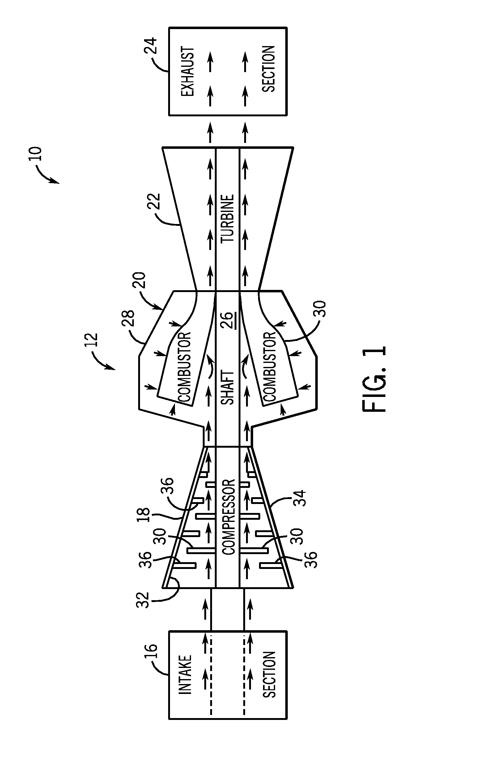
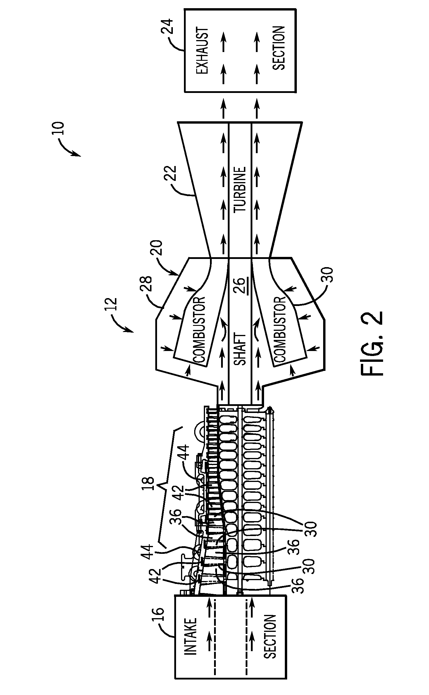
[0015]Embodiments of the invention include an inspection system to inspect internal components of a compressor of a gas turbine engine. The inspection system includes an image recording assembly having one or more image recording devices, light sources, storage devices, and power supplies. The image recording assembly may be inserted into a compressor without removal of the compressor housing or disassembly of the compressor. The image recording assembly may be removably coupled to a rotary component of the compressor, e.g., a rotor blade, and used to record images of stationary components, e.g., stator vanes, of the compressor. The image recording assembly may be removed from the compressor and the images may be provided to an image processing system for processing. The images may be inspected to identify wear and / or defects in the stationary components, e.g., stator vanes.

[0016]FIG. 1 is a block diagram of an exemplary system 10 including a gas turbine engine 12 that may be inspec...


PUM


Abstract

Embodiments of the invention include an inspection system to inspect internal components of a compressor of a gas turbine engine. The inspection system includes an image recording assembly having one or more image recording devices, light sources, storage devices, and power supplies. The image recording assembly may be inserted into a compressor without removal of the compressor housing or disassembly of the compressor. The image recording assembly may be removably coupled to a rotary component of the compressor, e.g., a rotor blade, and used to record images of stationary components, e.g., stator vanes, of the compressor. The images may be inspected to identify wear and / or defects in the stationary components, e.g., stator vanes

Description

BACKGROUND OF THE INVENTION[0001]The subject matter disclosed herein relates to gas turbine engines and, more particularly, to inspection of interior components of such turbine engines.[0002]In general, gas turbine engines combust a mixture of compressed air and fuel to produce hot combustion gases. The combustion gases may flow through one or more turbine stages to generate power for a load and / or a compressor. The compressor may include rotary components, such as rotors and blades that rotate about a shaft, and stationary components, such as stator vanes. Over time, the various components of the compressor of the gas turbine engine may wear or develop defects. Inspection of these components to determine wear and / or defects may be difficult due to the enclosure of the gas turbine engine.[0003]One technique for inspecting internal components of the gas turbine engine may include inserting a borescope through borescope holes to manually inspect different components, such as rotor bla...

Claims


Application Information

Patent Timeline
Patent Type & Authority Applications(United States)
IPC IPC(8): F02C7/00H04N7/18
CPCY02T50/671F01D21/003F01D25/285F05D2260/80F05D2270/8041G01N21/954G01N2021/8887Y02T50/60
Inventor GEORGE, SHERIJAMMU, VINAY BHASKARKUMAR, VINOD PADMANABHANMITRA, CHAYANGORAY, KUNAL RAVINDRAPANDEY, ACHALESH KUMARBABU, RAVI YOGANATHAKEELY, BHASKER RAOINAMDAR, MUNISH VISHWAS
Owner GENERAL ELECTRIC CO
Why Eureka
Eureka Blog
Learn More