Method for simulation of welding distortion

Inactive Publication Date: 2011-09-01
HITACHI LTD
View PDF0 Cites 20 Cited by
  • Summary
  • Abstract
  • Description
  • Claims
  • Application Information

AI Technical Summary

Benefits of technology

[0029]According to the present invention, both the improvement in calculation precision and the reduction o

Problems solved by technology

However, when a welded structure is large, a large number of elements are needed for an analysis model, and a long period of calculation time is necessary for the thermo-elastic-plastic analysis.
Therefore, the possibility of the application of this analysis is poor in some cases.
However, because a two-dimensional model cannot be applied to a welding distortion of a complex and large structure in many cases, application of this method is limited.
However,

Method used


Image

  • Method for simulation of welding distortion
  • Method for simulation of welding distortion
  • Method for simulation of welding distortion

Examples


example 1

[0067]Next, an explanation will be given of a first example in which the simulation method of this embodiment is applied to a welded structure having a specific shape defined.

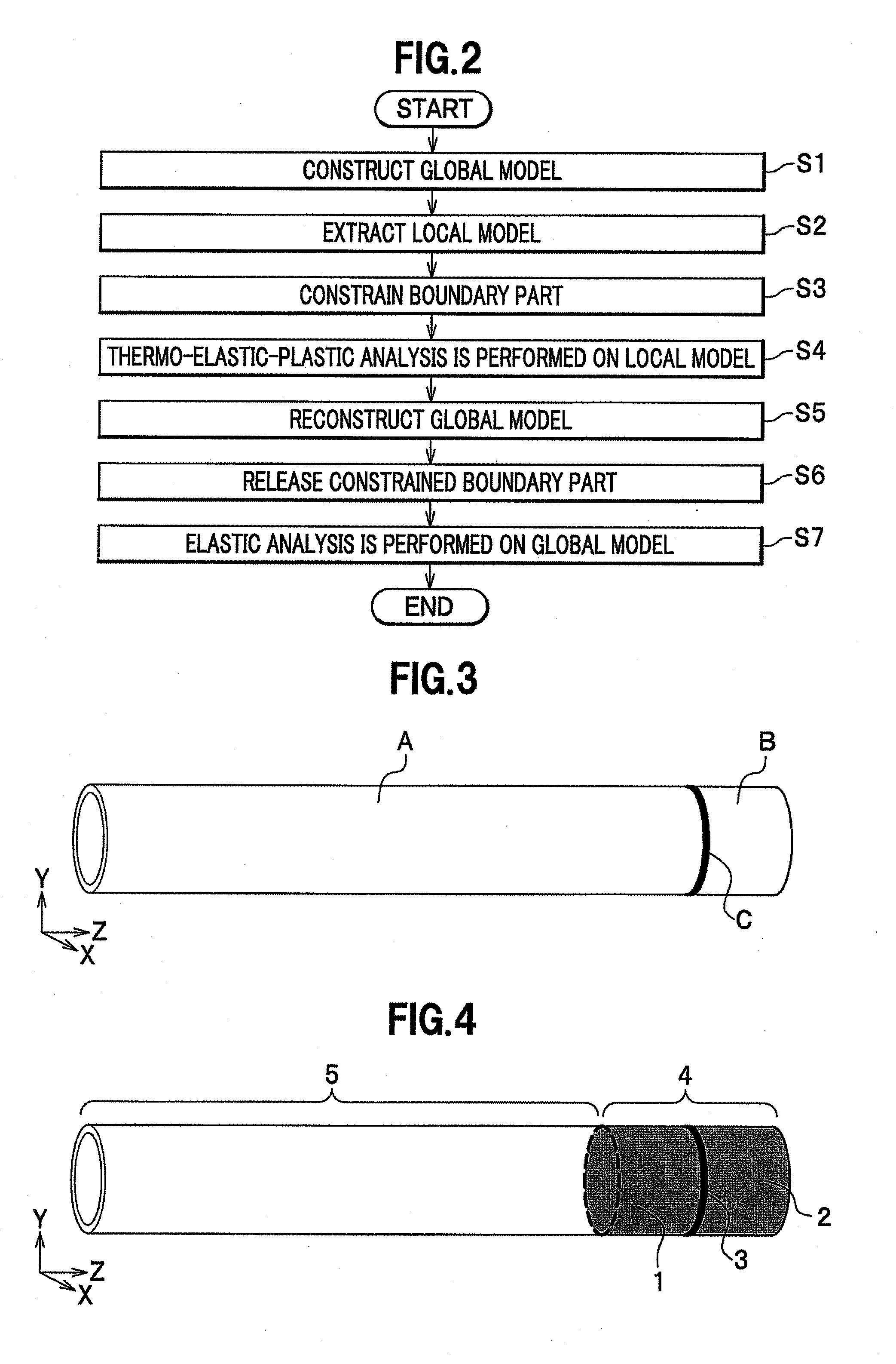
[0068]FIG. 3 is a diagram showing a configuration of a welded structure as an analysis target. The welded structure is a pipe structure, and includes a to-be-welded member A and a to-be-welded member B both joined by circumferential welding C. The structure after welding has a length of substantially 5 m, a diameter of substantially 200 mm and a thickness of 7 to 13 mm.

[0069]The welded structure shown in FIG. 3 is converted into a finite element model, thereby generating a three-dimensional model. A mesh generating step (a part of the process by the model generating / processing unit 142) is performed on this three-dimensional model, and a global model is constructed.

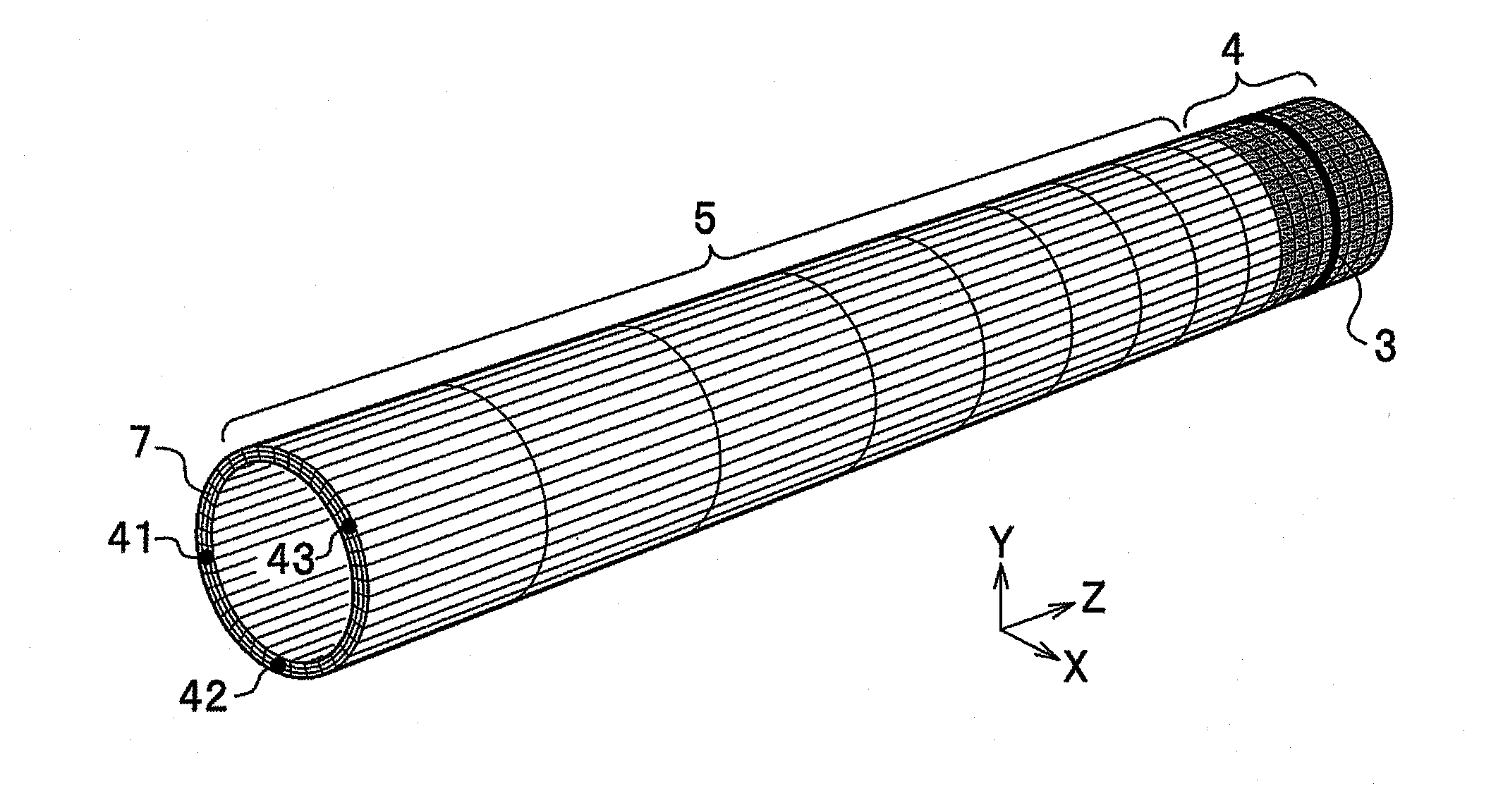
[0070]FIG. 4 is a diagram showing a global model of the welded structure shown in FIG. 3. The global model includes a local model 4 (a meshed part) ...

example 2

[0105]Next, an explanation will be given of a second example in which the simulation method of this embodiment is applied to a welded structure having a specific shape defined beforehand as another example. The second example relates to a case in which setting of the constraint condition for the boundary part in the first example is changed.

[0106]The analysis target in this example is a pipe-like welded structure shown in FIG. 3 which is same as the one used in the first example. Moreover, the simulation method is same as the first example other than a process relating to setting of the constraint condition of the boundary part. That is, the simulation method of the second example comprises a step of converting, through the step of generating a mesh, a structure subjected to analysis into a global model, and extracting a local model including a welded part needing a thermo-elastic-plastic analysis from the global model of the welded structure which is the analysis target and which n...


PUM


Abstract

It is an object of the present invention to accomplish both improvement of a calculation precision and reduction of a calculation time in prediction of a welding distortion of a large welded structure. A method of modeling a welded structure subjected to analysis by generating a mesh and performing thermo-elastic-plastic analysis thereon constructs a global model of the welded structure, and extracts a local model including a welded part from the global model. Next, the method constrains a boundary part of the extracted local model with the remaining portion of the global model, performs thermo-elastic-plastic analysis, and pastes the local model including the analysis result of the thermo-elastic-plastic analysis on the remaining portion of the global model, thereby reconstructing the global model. Thereafter, the method releases the constraint on the boundary part, and performs elastic analysis on the global model, thereby calculating a distortion of the welded structure.

Description

CROSS REFERENCE TO RELATED APPLICATION[0001]The present application claims benefit of the filing date of Japanese Patent Application No. 2010-022232 filed on Feb. 3, 2010, the disclosure of which is incorporated herein by reference.BACKGROUND OF THE INVENTION[0002]1. Field of the Invention[0003]The present invention relates to a method for calculating a distortion of a welded structure (hereinafter, may be simply referred to as a “structure” in some cases) and a residual stress thereof, etc., through a numerical analysis.[0004]2. Description of the Related Art[0005]When a large structure is made through welding, a welding distortion is produced because of thermal accumulation to the vicinity of a welded part and cooling thereafter. In order to reduce such welding distortion, in general, attachment of a restraint jig and reformation after welding are performed. According to such a situation, it is very important to predict a distortion through a numerical analysis like a finite eleme...

Claims


Application Information

Patent Timeline
IPC IPC(8): G06F17/50
CPCG06F2217/80G06F17/5018G06F30/23G06F2119/08
Inventor ZHANG, XUDONG
Owner HITACHI LTD
Why Eureka
Try Eureka