
Methods and apparatus for optimizing concurrency in multiple core systems

a technology of concurrency and core system, applied in the direction of multi-programming arrangement, program control, instruments, etc., can solve the problem of limited space for circuitry, and achieve the effect of improving overall system performan

Inactive Publication Date: 2011-09-01
META PLATFORMS TECH LLC
View PDF17 Cites 22 Cited by
  • Summary
  • Abstract
  • Description
  • Claims
  • Application Information

AI Technical Summary

Benefits of technology

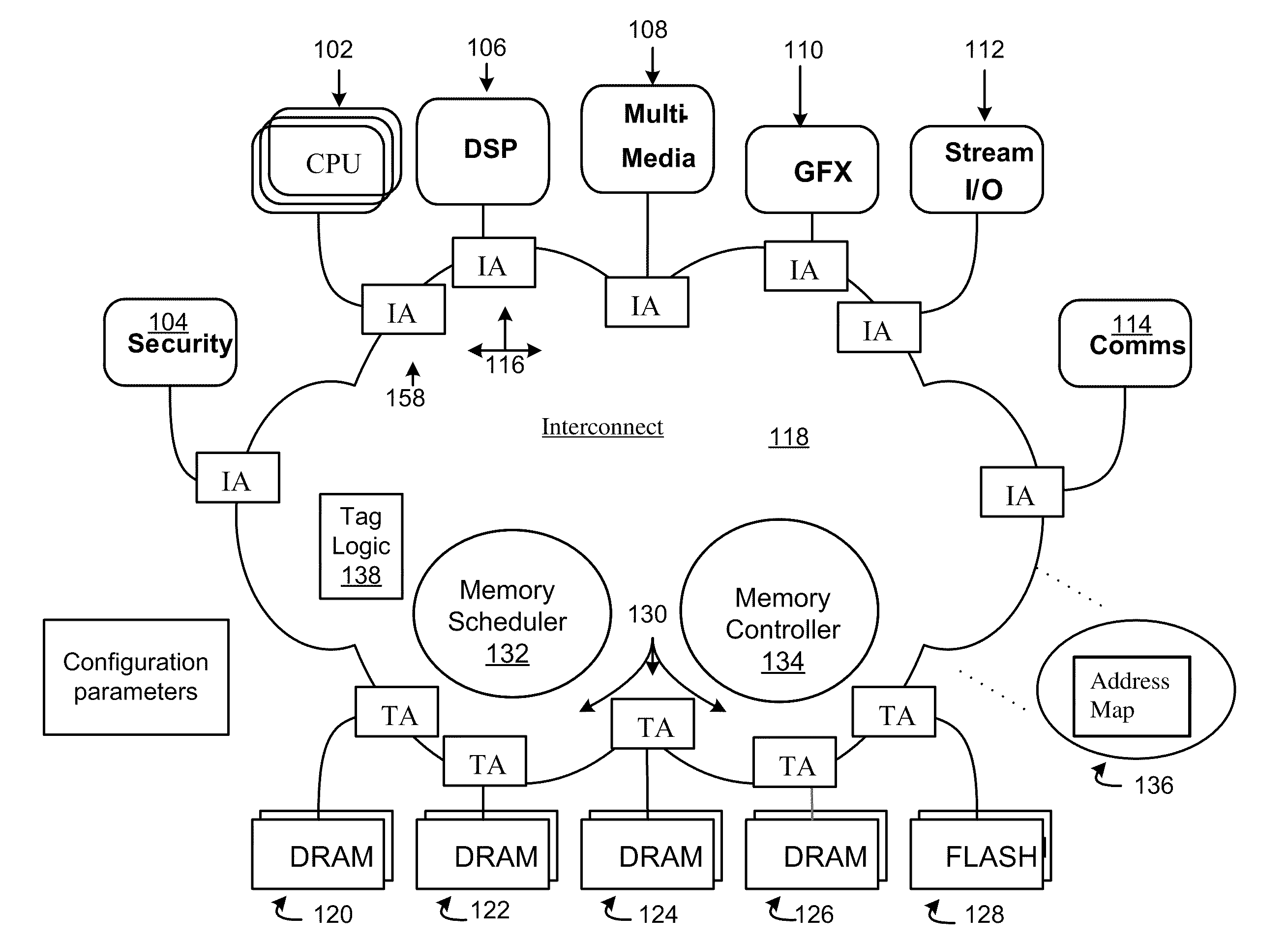
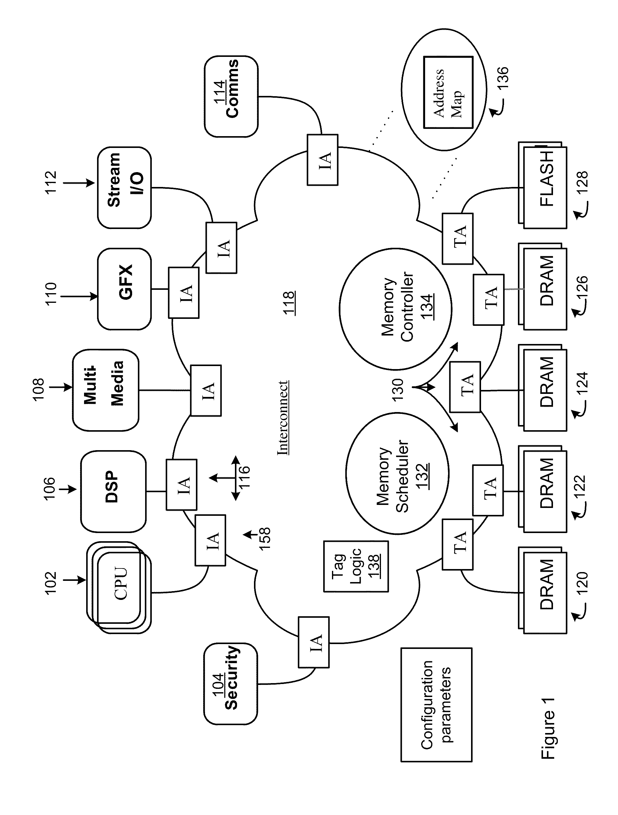
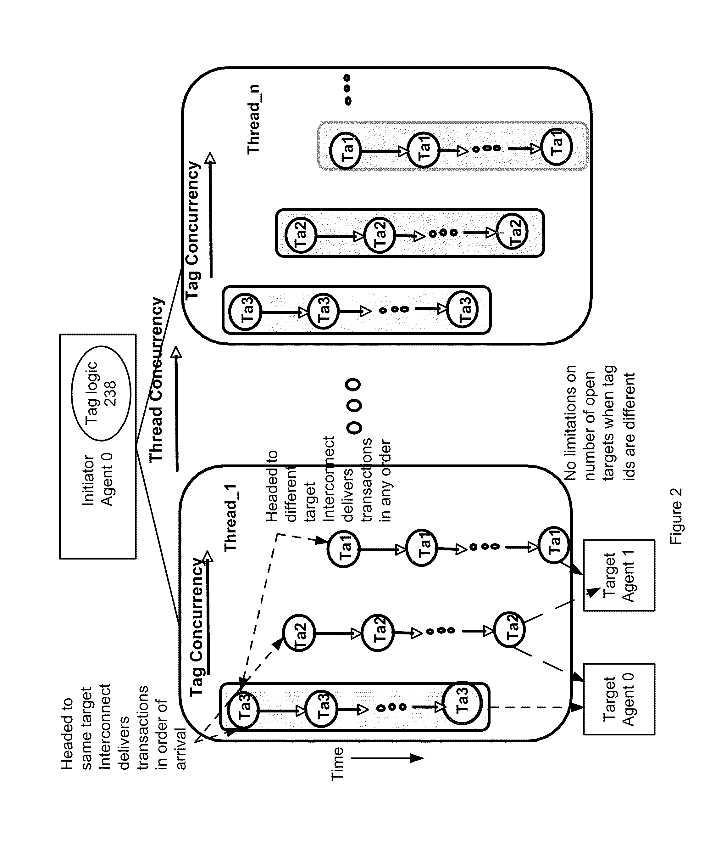
[0004]Various methods and apparatus are described for communicating transactions between one or more initiator IP cores and one or more target IP cores coupled to an interconnect. Tag logic may be located within the interconnect, such as located in an agent, and configured to assign different interconnect tag identification numbers to two or more transactions from a same thread from a first multiple threaded initiator IP core. The tag logic assigns different interconnect tag identification numbers to improve overall system performance by allowing the two or more transactions from the same thread of a first multiple threaded initiator IP core to be outstanding over the interconnect to two or more different target IP cores at the same time. The tag logic is further configured to allow the two or more transactions from the same thread to be processed in parallel over the interconnect and potentially serviced out of issue order while being returned back to the first multiple threaded initiator IP core realigned in expected execution order. This eliminates any need for a re-order buffer per thread per initiator core. An interconnect tag identification number can be used to link a response to a transaction with a thread generating the transaction that triggered the response from a first target IP core.

Problems solved by technology

In integrated circuit, a limited amount of space to house the circuitry may exist in that integrated circuit.

Method used


Image

  • Methods and apparatus for optimizing concurrency in multiple core systems
  • Methods and apparatus for optimizing concurrency in multiple core systems
  • Methods and apparatus for optimizing concurrency in multiple core systems

Examples


Embodiment Construction

[0018]In the following description, numerous specific details are set forth, such as examples of specific data signals, named components, connections, number of memory channels in an aggregate target, etc., in order to provide a thorough understanding of the present invention. However, it will be apparent to a person of ordinary skill in the art that the present invention may be practiced without these specific details. In other instances, well known components or methods have not been described in detail, but rather in a block diagram in order to avoid unnecessarily obscuring the present invention. Further, specific numeric references, such as first target, may be made. However, the specific numeric reference should not be interpreted as a literal sequential order, but rather interpreted that the first target is different than a second target. Thus, the specific details set forth are merely exemplary. The specific details may be varied from, and still be contemplated to be, within ...


PUM


Abstract

Various methods and apparatus are described for communicating transactions between one or more initiator IP cores and one or more target IP cores coupled to an interconnect. Tag logic may be located within the interconnect, such as located in an agent, and configured to assign different interconnect tag identification numbers to two or more transactions from a same thread. The tag logic assigns different interconnect tag identification numbers to allow the two or more transactions from the same thread to be outstanding over the interconnect to two or more different target IP cores at the same time, allow the two or more transactions from the same thread to be processed in parallel over the interconnect, and potentially serviced out of issue order while being returned back to the multiple threaded initiator IP core realigned in expected execution order.

Description

NOTICE OF COPYRIGHT[0001]A portion of the disclosure of this patent document contains material that is subject to copyright protection. The copyright owner has no objection to the facsimile reproduction by anyone of the software engine and its modules, as it appears in the Patent and Trademark Office Patent file or records, but otherwise reserves all copyright rights whatsoever.FIELD OF THE INVENTION[0002]Embodiments of the invention generally relate to methods and apparatus for optimizing concurrency in multiple Intellectual Property core systems including target and initiator cores.BACKGROUND OF THE INVENTION[0003]In integrated circuit, a limited amount of space to house the circuitry may exist in that integrated circuit. A tradeoff occurs between increasing an amount of transactions being processed over a given period of time and the increase in area occupied by the logic and buffering required to allow a higher amount of transactions being processed over a given period of time.S...

Claims


Application Information

Patent Timeline
IPC IPC(8): G06F15/76G06F12/00G06F9/46
CPCG06F15/173
Inventor JAYASIMHA, DODDABALLAPUR N.TON, LUC HOAWINGARD, DREW E.
Owner META PLATFORMS TECH LLC
Learn More