Electric Pest Deterrent Tracks and Systems

a technology of electric pests and tracks, applied in the field of pest repelling technologies, can solve the problems of driving the pest away, receiving unpleasant electrical shocks, and not providing a sufficient deterrent from crawling creatures or birds

Inactive Publication Date: 2011-09-08
BIRD B GONE
View PDF34 Cites 32 Cited by
  • Summary
  • Abstract
  • Description
  • Claims
  • Application Information

AI Technical Summary

Benefits of technology

[0012]The inventive subject matter provides apparatus, systems and methods in which a pest deterrent system comprises an electrical deterrent track having a single conductor strip. One aspect of the inventive subject matter includes a pest deterrent system comprising multiple electric deterrent tracks. In some embodiments each of the tracks includes an elongated insulator base having a conducting strip running the length of the base. The conducting strip can be affixed to the base using various suitable techniques including sewing, adhesives, friction fits, or other techniques. The insulator bases of the tracks can also include one or more base connectors that allow the base to couple to other bases, which allows for placement of the tracks in many different configurations on an installation surface. For example, two tracks could be placed next to each other to form a linear dual conductor deterrent system. Two or more tracks can also be arranged in other configurations to cover an area. The system can further include a power coupling assembly capable of supplying a voltage different between adjacent conducting strips of the tracks.
[0013]In more preferred embodiments, the tracks are fungible with respect to each other, where each track's base can comprise continuous base connectors running the length of the track, possibly formed during an extrusion process at the time of manufacture. Such a configuration allows one track to couple to other tracks, or itself, along the length of the base. It is also contemplated that spacers, possibly an elongated base lacking a conductor, can be disposed between tracks so the resulting deterrent system has proper spacing for a target pest. Different sized spacers can be deployed to adjust the spacing to target different pests.
[0014]Another aspect of the inventive subject matter includes an electrical deterrent track comprising an elongated insulator base having one or more base connectors. One or more conducting strips can be affixed to a top surface of the base. Preferably the base connectors can couple with bases of other tracks or spacers. Preferably a track comprises a single conducting strip.
[0015]Various objects, features, aspects and advantages of the inventive subject matter will become more apparent from the following detailed description of preferred embodiments, along with the accompanying drawing figures in which like numerals represent like components.

Problems solved by technology

When a pest (e.g., insect, slug, bird, animal, etc.) comes into contact with both of the conductors, the pest receives an unpleasant electrical shock thus driving the pest away.
Although the above technologies aid in controlling large animals, the technologies do not provide a sufficient deterrent from small crawling creatures or birds.
Such systems would likely deter small, crawling creatures, but still fail to address birds.
Such a system would likely be unpractical.
Such a system requires production of many different shaped bases, which would be impractical and would lack flexibility for varied installation geometries.
International patent application publication WO 95 / 08915 also to Greenwood titled “Deterrent Arrangement”, filed Sep. 30, 1994, suggests placing exposed wires within an elongated flexible base, but still suffers from lack of lateral flexibility without stressing the conductors.
Unfortunately, bending laterally places undue stress on the conducting elements, especially the elements disposed on an outer radius of the flex.
Still, such an approach is limited by the amount of crimp provided.
Unfortunately, the approach suggest by Bailey requires significant expertise and care when installing the conductors to ensure the conductors have proper spacing between them.
Unfortunately, such a system lacks laterally flexibility due to the width of the base, and the tightly braided conductors restrict evaporation of water resulting from inclement weather.
Unfortunately, the Riddell and Donoho devices lack lateral flexibility (e.g., flex in a plane parallel to the base), as with the Greenwood approaches.
The result is that each existing product solution suffer from many different issues due to the restrictive nature of the designs.
One issue with the know art includes a lack of ability to address a varied installation topology or geometry.
For example, although the Riddell solution can bend vertically around corners, the solution fails to bend horizontally due to the base width.
Even if it could, the stress on the conductor at the outer radius of the bend would likely pop the conductor's stitching.
Another issue with configurations having a single insulator base having plural conductors is that the spacing between the conductors is set at manufacturing time and restricts the adaptability of the device to target a variety of pests (e.g., crawling creatures, different sized birds, etc.).
Yet another issue with known devices includes lack of modularity where devices can be combined as desired during installation in a manner to cover an area of a surface.
However, Burdick's bases are rigid and fail to provide flexibility to cover an area efficiently.

Method used


Image

  • Electric Pest Deterrent Tracks and Systems
  • Electric Pest Deterrent Tracks and Systems
  • Electric Pest Deterrent Tracks and Systems

Examples


Embodiment Construction

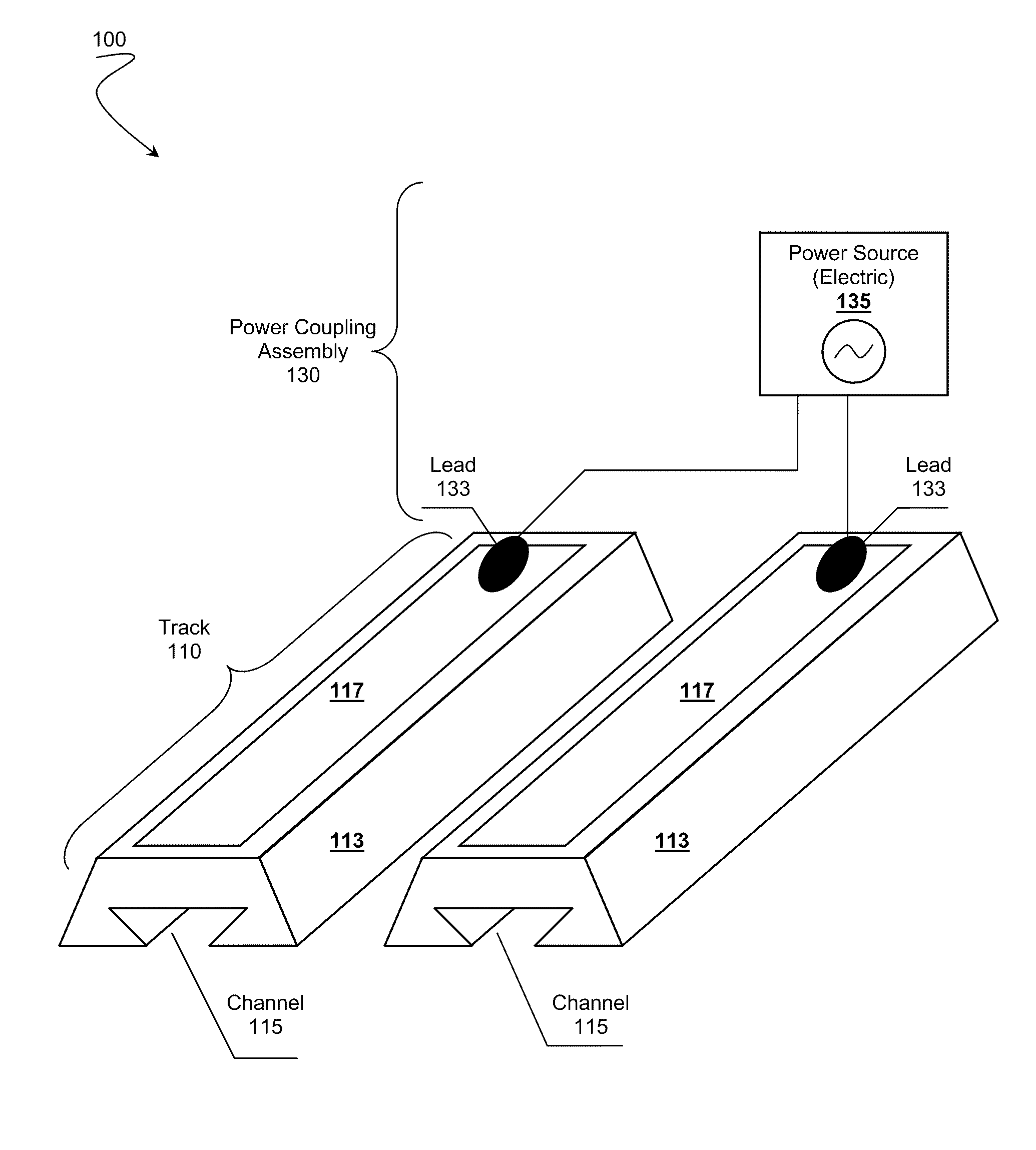
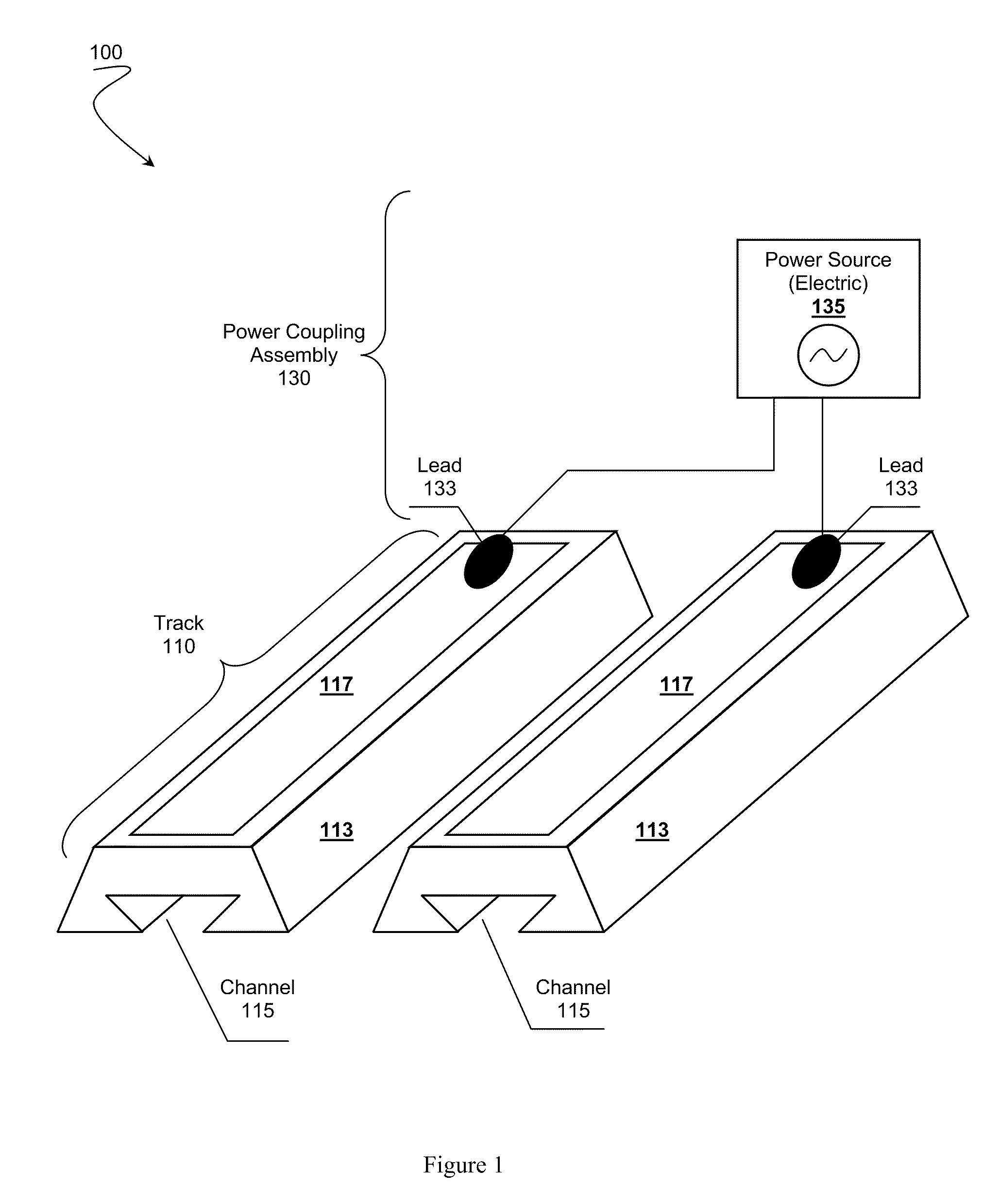
[0023]The following discussion presents one or more aspects of the inventive subject matter from a perspective of deterring birds. One should appreciate that the disclosed techniques can be readily adapted to target many different pests including insects, rodents, gastropods, birds of various sizes, large animals, or other pests.

[0024]In FIG. 1, system 100 provides a basic overview relating to features of an electrical deterrent system that comprises at least two of electric deterrent track 110 and power coupling assembly 130. System 100 can include a plurality of tracks 110 arranged according to various configurations. In the example shown, two of tracks 110 are arranged adjacent to each other on an installation surface (e.g., roof, building, boat, etc.).

[0025]Electrical deterrent tracks 110 can comprise a conducting strip 117 affixed to a top surface of insulator base 113. Strip 117 can be affixed through various suitable approaches including mechanical fasteners (e.g., staples, s...


PUM


Abstract

Electrical deterrent systems are presented. A deterrent system can include electrical deterrent tracks comprising an insulator base and a conducting strip affixed to a top surface of the track. The bases can include one or more base connectors that allow tracks to be joined together in various configurations including area covering arrays. The conducting strips can be woven, non-woven, meshes, or other types of conductors.

Description

FIELD OF THE INVENTION[0001]The field of the invention is pest repelling technologies.BACKGROUND[0002]Electrical pest deterrent devices generally include two parallel electrical conductors placed near each other, where the conductors have a voltage difference between them. When a pest (e.g., insect, slug, bird, animal, etc.) comes into contact with both of the conductors, the pest receives an unpleasant electrical shock thus driving the pest away. Pests hopefully learn to avoid the deterrent, or the area.[0003]A great deal of past effort has been directed to developing different types of electrical pest deterrents. For example, many technologies have been developed relating to electric fences to prevent large animals from crossing a boundary. Japanese patent application publications to Koyama JP 2001 000163 titled “Engergizable Electric Net for Preventing Animal”, filed Jun. 19, 2000; and JP 2003 219788 titled “animal Barrier System, Net for Animal Barrier and Ring for Fixing Animal...

Claims


Application Information

Patent Timeline
Patent Type & Authority Applications(United States)
IPC IPC(8): A01M1/22H05C3/00A01M23/38
CPCA01M23/38H05C3/00A01M1/22A01M29/24A01K3/005
Inventor DONOHO, BRUCE
Owner BIRD B GONE
Why Eureka
Try Eureka