Flow restriction insert for differential pressure measurement

a technology of restrictor insert and differential pressure, which is applied in the direction of instruments, surveying, and wellbore/well accessories, etc., can solve the problems of less accurate differential pressure output, less, if any, of insert devices, and inability to be permanently removed by destruction, etc., and achieve the effect of reducing the cross-sectional area of restrictor

Inactive Publication Date: 2011-09-08
SCHLUMBERGER TECH CORP
View PDF10 Cites 32 Cited by
  • Summary
  • Abstract
  • Description
  • Claims
  • Application Information

AI Technical Summary

Benefits of technology

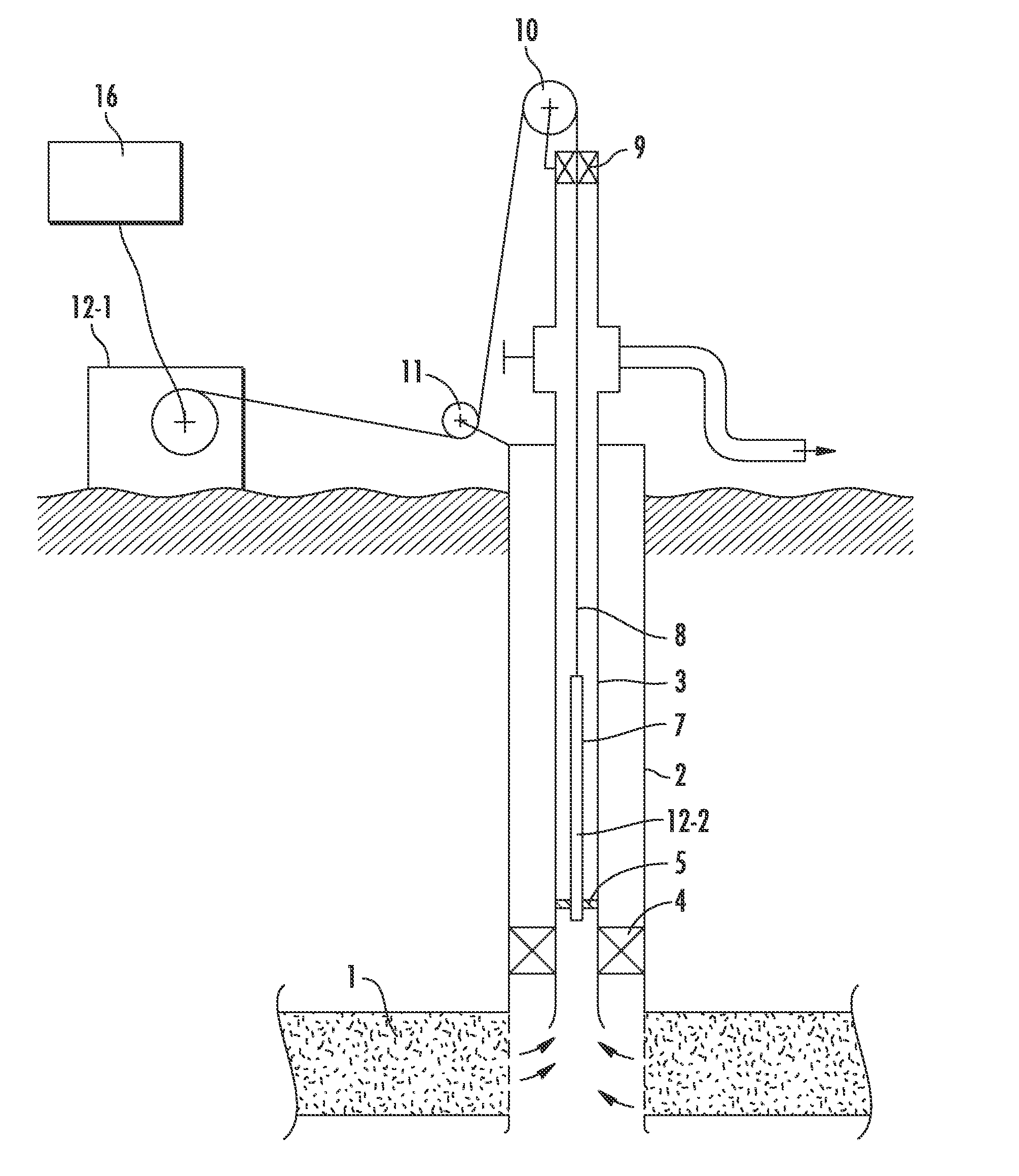
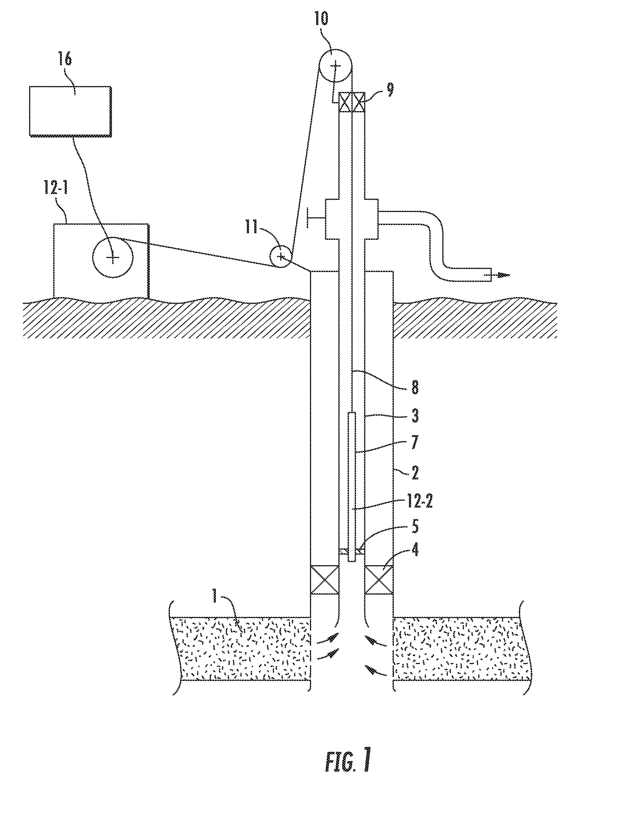
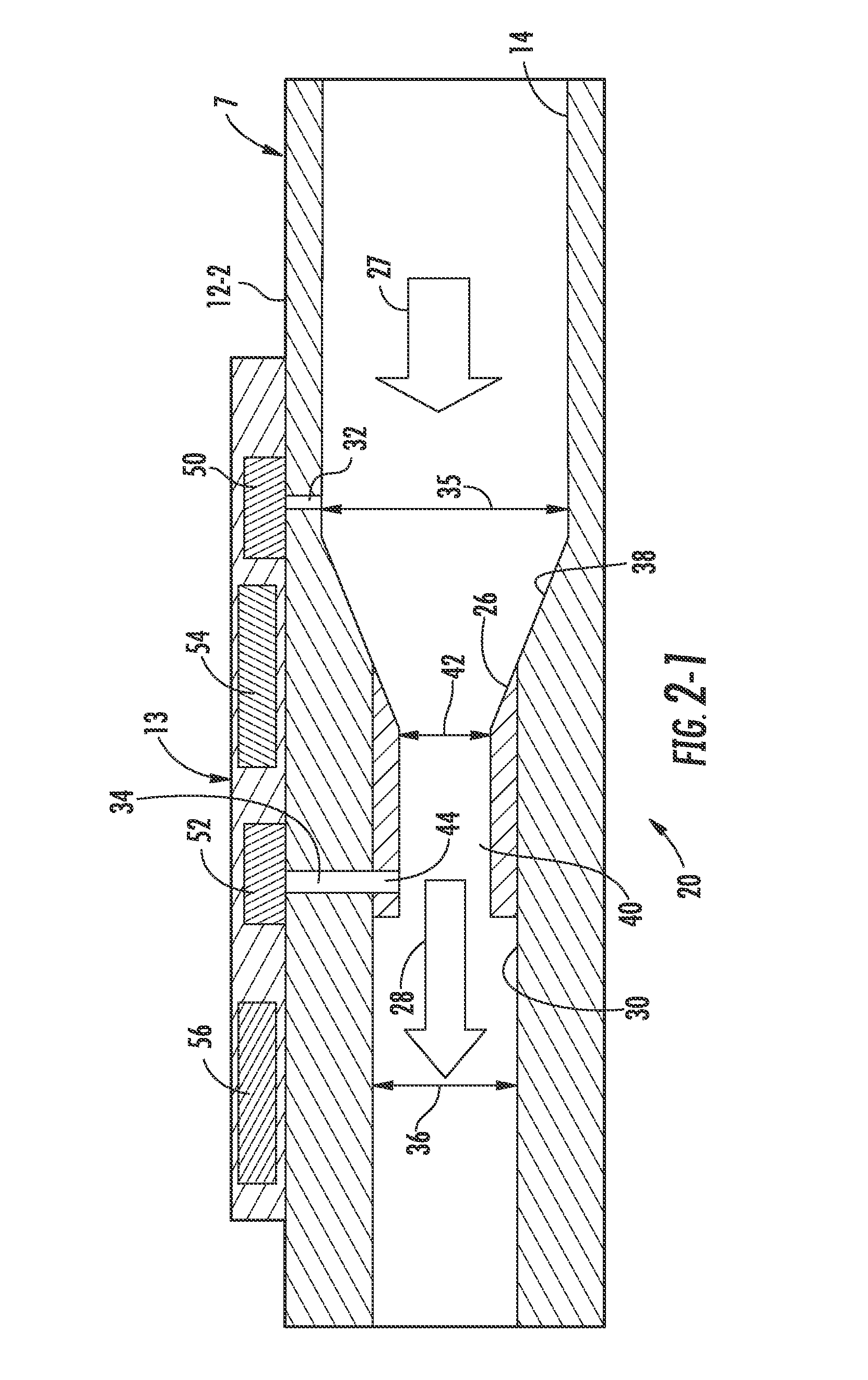
[0012]In one aspect, the present invention is directed to a flow rate device for measuring the flow rate of a fluid flowing through a wellbore. The flow rate device includes a differential pressure conduit, a flow restrictor insert and a differential pressure measurement device. The differential pressure conduit is locatable in the wellbore, defines an internal bore, and is adapted to include a restriction having a cross-sectional area to increase the velocity of fluid flowing through the differential pressure conduit to create a differential pressure. The differential pressure conduit defining first and second pressure measuring stations axially spaced along the differential pressure conduit. The flow restrictor insert is located in the restriction to reduce the cross-sectional area of the restriction. The flow restrictor insert defines an internal bore having a cross-sectional area less than the cross-sectional area of the restriction. The flow restrictor insert also has a pressure measuring port aligned with the second pressure measuring station. The differential pressure measurement device may have first and second pressure sensors with the first pressure sensor measuring the pressure at the first pressure station, and the second pressure sensor measuring the pressure at the second pressure station for generating a signal indicative of the flow rate of the fluid. Alternatively, the differential pressure measurement device may have a differential pressure sensor adapted to measure the difference between the pressure at the first pressure station and the pressure at the second pressure station for generating a signal indicative of the flow rate of the fluid.

Problems solved by technology

There are a number of current systems available to measure the fluid flow rate flowing from a well, but few, if any, of them can be constructed “in-line,” to allow reliable, unobtrusive measurements to be taken within the wellbore at a location near the reservoir.
Moreover, the insert device is not particularly adapted to be permanently removed by destruction so as to not interfere with wellbore operations.
At this throat size, the differential pressure output is less accurate at low flow rates (e.g., <2,000 bbl / d).
Further, restrictions below 2.25 inches can either cause blockage or limit the selection of tools that may be used when deploying tools down / up a production well.

Method used


Image

  • Flow restriction insert for differential pressure measurement
  • Flow restriction insert for differential pressure measurement
  • Flow restriction insert for differential pressure measurement

Examples


Embodiment Construction

[0027]Specific embodiments of the present invention will now be described in detail with reference to the accompanying drawings. Further, in the following detailed description of embodiments of the present invention, numerous specific details are set forth in order to provide a more thorough understanding of the present invention. However, it will be apparent to one of ordinary skill in the art that the embodiments disclosed herein may be practiced without these specific details. In other instances, well-known features have not been described in detail to avoid unnecessarily complicating the description.

[0028]The terminology and phraseology used herein is solely used for descriptive purposes and should not be construed as limiting in scope. Language such as “including,”“comprising,”“having,”“containing,”“consisting of,” or “involving,” and variations thereof, is intended to be broad and encompass the subject matter listed thereafter, equivalents, and additional subject matter not re...


PUM


Abstract

A flow rate device for measuring the flow rate of a fluid flowing through a wellbore is disclosed. The flow rate device includes a differential pressure conduit, a flow restrictor insert and a differential pressure measurement device. The differential pressure conduit is locatable in the wellbore, defines an internal bore, and is adapted to include a restriction having a cross-sectional area to increase the velocity of fluid flowing through the differential pressure conduit to create a differential pressure. The differential pressure conduit defining first and second pressure measuring stations axially spaced along the differential pressure conduit. The flow restrictor insert is located in the restriction to reduce the cross-sectional area of the restriction. The flow restrictor insert defines an internal bore having a cross-sectional area less than the cross-sectional area of the restriction. The flow restrictor insert also has a pressure measuring port aligned with the second pressure measuring station. The differential pressure measurement device has at least one pressure sensor for detecting the pressure at the first pressure station, and for detecting the pressure at the second pressure station to generate a signal indicative of the flow rate of the fluid.

Description

BACKGROUND[0001]1. Technical Field[0002]The present invention relates to an apparatus and method for improving the sensitivity of a flow rate device measuring the flow rate of a fluid in a hydrocarbon well. More particularly, but not by way of limitation, the present invention relates to a flow restrictor insert that can be installed in a restriction of a differential pressure measurement device to increase the velocity of the fluid as it passes through the restriction and can be permanently removed by destruction while maintaining the operability of the flow rate device albeit at a lower sensitivity.[0003]2. Background Art[0004]Flow rate devices, or flow meters, are widely used in the oil and gas, and petrochemical industries. The ability of the oil and gas industry to optimize production of a reservoir relies on the possibility of evaluating the well effluent (i.e. oil, gas and water), at regular intervals, in terms of quantity (flow rate) and of composition (the proportions of th...

Claims


Application Information

Patent Timeline
Patent Type & Authority Applications(United States)
IPC IPC(8): E21B47/10G01F1/42G01F1/44
CPCG01F1/44E21B47/10
Inventor REZGUI, FADHELROUX, GILLESINGHAM, ROBERTFILAS, JIMMANIN, YVESDONZIER, ERIC
Owner SCHLUMBERGER TECH CORP
Why Eureka
Try Eureka