Bonding apparatus and bonding method

a technology of bonding apparatus and bonding method, which is applied in the direction of chemistry apparatus and processes, other domestic articles, layered products, etc., can solve the problems of void generation between the wafers, warping or cracks in the wafers, and preventing so as to achieve efficient bonding operation and prevent the generation of voids between the members

Inactive Publication Date: 2011-09-08
TOKYO ELECTRON LTD
View PDF8 Cites 53 Cited by
  • Summary
  • Abstract
  • Description
  • Claims
  • Application Information

AI Technical Summary

Benefits of technology

[0031]According to the present invention, when two members are bonded to each other, generation of voids between the members may be prevented and the bonding operation may be performed efficiently.

Problems solved by technology

For example, when a thin wafer having a large diameter is conveyed or polished, the wafer may be warped or cracks may be generated in the wafer.
However, when the wafers are bonded to each other in a state where the adhesive is disposed between the wafers, voids may be generated between the wafers.

Method used


Image

  • Bonding apparatus and bonding method
  • Bonding apparatus and bonding method
  • Bonding apparatus and bonding method

Examples


Embodiment Construction

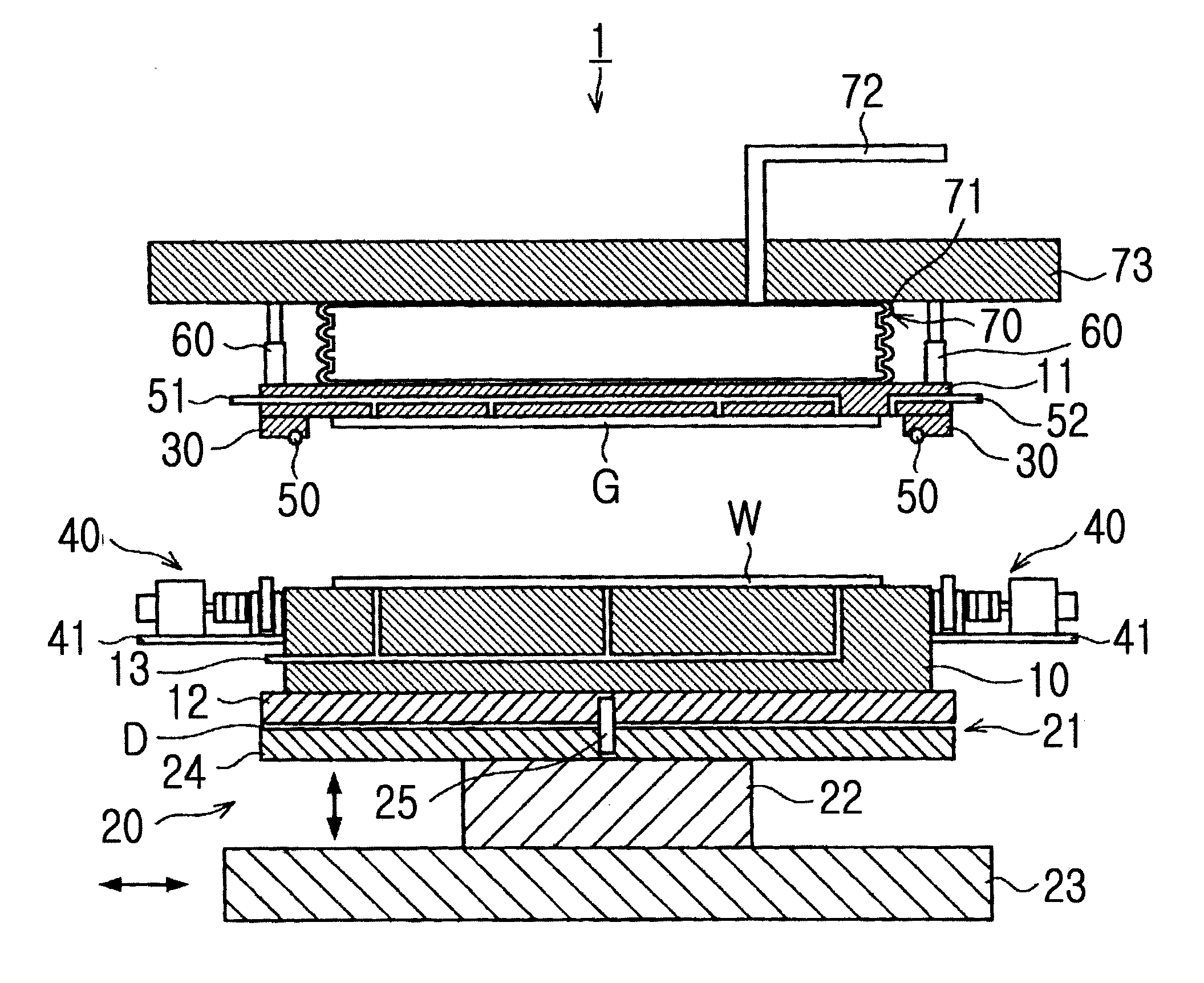
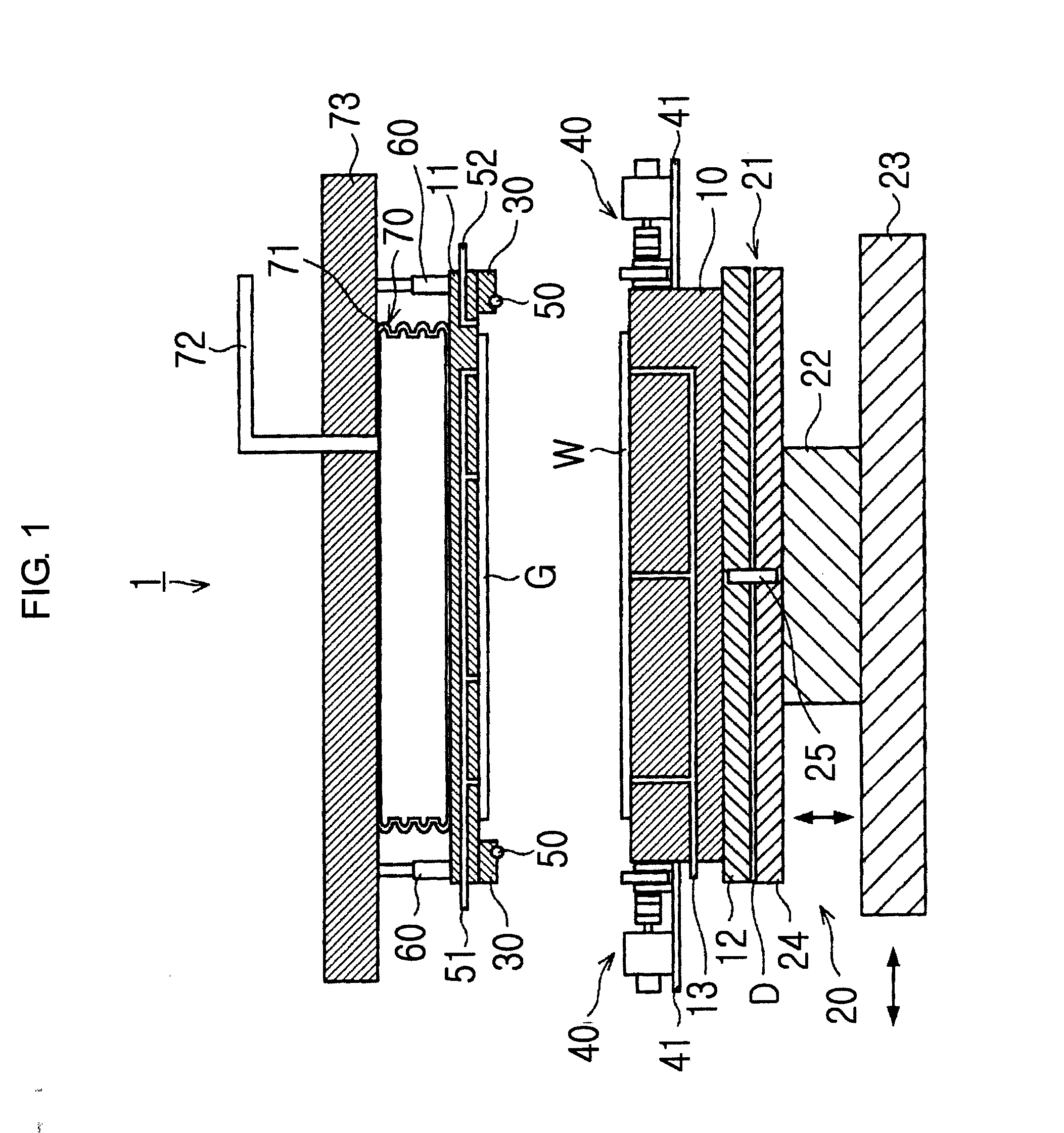
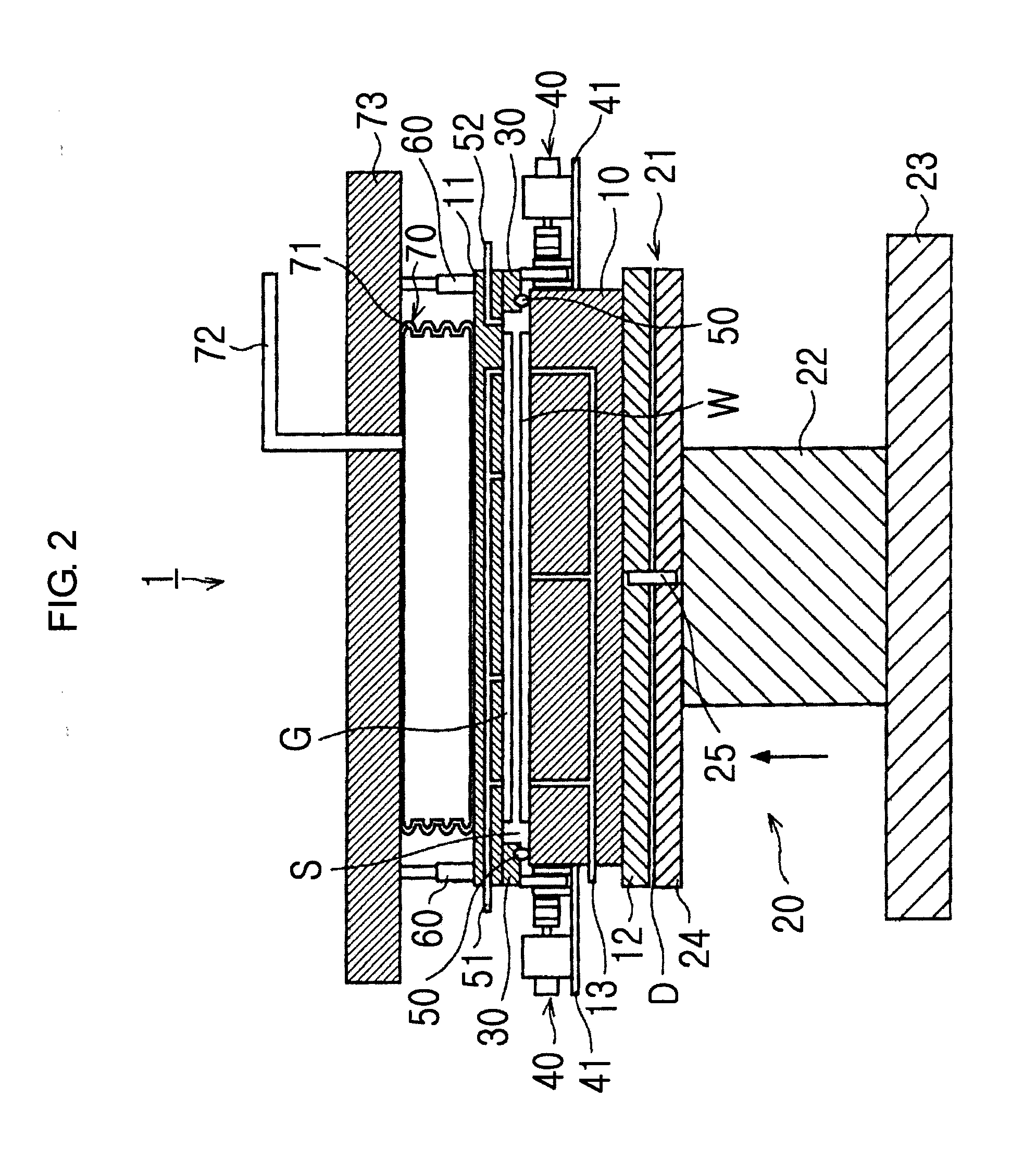
[0079]Hereinafter, embodiments of the present invention will be described as follows. FIGS. 1 and 2 are schematic longitudinal-sectional views showing a configuration of a bonding apparatus 1 according to an embodiment of the present invention.

[0080]The bonding apparatus 1 includes a lower chuck 10 as a part of a first holding section that places and holds a wafer W, that is, a first member, on an upper surface thereof, and an upper chuck 11 as a second holding section that adsorbs and holds a glass substrate G, that is, a second member, on a lower surface thereof. The upper chuck 11 is formed above and facing the lower chuck 10. That is, the wafer W held by the lower chuck 10 and the glass substrate G held by the upper chuck 11 face each other. A rotating table 12 that supports the lower chuck 10 and freely rotates in a horizontal direction is formed on a lower surface of the lower chuck 10. In addition, the lower chuck 10 and the rotating table 12 form the first holding section. A...


PUM

PropertyMeasurementUnit
diameteraaaaaaaaaa
pressureaaaaaaaaaa
pressureaaaaaaaaaa

Abstract

A bonding apparatus includes a first holding section which places and holds a first member on an upper surface, and a second holding section which adsorbs and holds a second member on a lower surface. The second holding section is configured such that a center section bends due to a predetermined pressure. The second holding section includes an intake mechanism which sucks atmosphere of a bonding space between the first holding section and the second holding section. A protrusion which protrudes downward along an outer circumferential lower surface of the second holding section is formed on the outer circumferential lower surface. A sealing member which holds an air-tightness of the bonding space and has elasticity is formed in a lower surface of the protrusion. A height adjusting mechanism which abuts on the protrusion and can adjust the vertical distance between the first member and the second member is formed on a side surface of the first holding section.

Description

TECHNICAL FIELD[0001]The present invention relates to a bonding apparatus for bonding two members formed as thin plates, and a bonding method using the bonding apparatus.BACKGROUND ART[0002]Recently, in processes of manufacturing semiconductor devices or micro electro mechanical systems (MEMSs), semiconductor wafers (hereinafter, referred to as “wafers”) have been fabricated with large diameters. In addition, in a certain process such as a mounting process, a thin wafer is required. For example, when a thin wafer having a large diameter is conveyed or polished, the wafer may be warped or cracks may be generated in the wafer. Therefore, in order to reinforce the wafer, for example, the wafer may be adhered to another wafer or a glass substrate as a reinforcing substrate.[0003]Bonding of the above-described wafers is performed by disposing an adhesive between the wafers. However, when the wafers are bonded to each other in a state where the adhesive is disposed between the wafers, voi...

Claims


Application Information

Patent Timeline
Patent Type & Authority Applications(United States)
IPC IPC(8): B32B37/10B32B37/02B32B37/06B32B37/14B32B37/16
CPCB32B37/003B32B37/10Y10T156/17H01L21/67092B32B2457/00
Inventor SUGIYAMA, MASAHIKO
Owner TOKYO ELECTRON LTD
Why Eureka
Try Eureka